

Effective HVAC noise control comes down to three moves executed in order: specify quiet equipment at the source, block or absorb the transmission path, and protect the occupied space at the receiver. Most persistent noise complaints trace back to skipping one of these three, usually the path, because it is the step most often value-engineered out of a project budget. ASHRAE frames this as the source–path–receiver approach, and it remains the organizing principle behind every credible noise-control specification in commercial and residential mechanical design.
The one-line verdict for most complaints: if the noise correlates with equipment speed and disappears when the unit cycles off, you are usually looking at a source or path problem solvable with re-balancing or a retrofit silencer. If the sound is a persistent low-frequency rumble independent of airflow, or it affects sensitive occupied spaces like a recording studio, hospital ward, or executive boardroom, escalate to an acoustical or MEP engineer before spending money on lining and blankets that will not fix a structural transmission issue.
Run these three checks before touching a toolbox:
- Visual inspection first. Look for loose panels, missing isolation pads, crushed flex connectors, and duct sag near the air handling unit.
- Basic spectrum check. A handheld sound level meter with octave-band capability tells you whether the complaint is low-frequency (mechanical/structural) or mid-to-high frequency (airflow-generated).
- Compare against NC criteria. Match the measured spectrum to the Noise Criteria (NC) curve appropriate for the space type; an office typically targets NC-30 to NC-40, while a boardroom or bedroom often needs NC-25 or lower.
Pro Tip: Cup your hand around your ear and slowly walk the duct run from the air handler to the diffuser. Mechanical noise stays constant in level as you move away from the unit and only drops with distance; flow noise gets noticeably louder near sharp elbows, dampers, or undersized branch takeoffs, even far from the fan. That five-minute walk-through often resolves a misdiagnosis that would otherwise send a crew chasing the wrong fix for a week.
Most HVAC noise complaints are not equipment failures. They are system-integration failures: the right components installed without accounting for how the path and the receiving room interact with them.
Key Takeaways
Effective HVAC noise control requires diagnosing the correct noise path first, then applying source, path, or receiver mitigations matched to measurable acceptance criteria like NC curves and ASTM-tested performance data.
| Point | Details |
|---|---|
| Diagnose before treating | Distinguish mechanical, airflow, and structureborne noise before selecting any fix. |
| Measure with octave-band data | A-weighted numbers alone hide the low-frequency issues that cause most rumble complaints. |
| Respect clearances | Keep silencers and branch takeoffs the recommended duct diameters from turbulence sources. |
| Budget for prevention | Design-stage noise control typically adds only 1 to 2 percent of total HVAC cost, far less than a retrofit. |
| Escalate red-flag cases | Bring in an MEP or acoustical engineer, such as Futuregenconsulting, for low-frequency rumble under NC-30 or health-critical spaces. |
Table of Contents
- What Are the Main Types of HVAC Noise?
- How Do You Measure and Diagnose HVAC Noise Problems?
- What Mitigation Methods Work for Each Noise Path?
- How Do You Select the Right Silencer, Lining, or Isolator?
- Where Should Silencers and Isolation Be Placed for Best Performance?
- Which Codes and Standards Govern HVAC Noise Control?
- What Belongs in a Noise-Control Spec and Commissioning Plan?
- What Are the Quick Fixes When Tenants Complain About HVAC Noise?
- When Should You Bring In an Acoustical or MEP Engineer?
- Where Noise Control Projects Actually Go Wrong
- How Futuregenconsulting Supports HVAC Noise Control Projects
- Frequently Asked Questions About HVAC Noise Control
- Sources
What Are the Main Types of HVAC Noise?
HVAC noise falls into three categories, and each one demands a different diagnostic path and fix. Confusing them is the single most common reason retrofit spending fails to solve a complaint.
Mechanical (equipment) noise originates at the fan, compressor, motor, or bearings. It typically presents as a tonal hum, whine, or rattle tied directly to rotational speed, and it often carries strong low-frequency content in the 31 to 125 Hz octave bands.
Airflow or ductborne noise is generated by turbulence: air moving too fast through undersized ducts, past sharp elbows, through partially closed dampers, or out of poorly designed diffusers. Field practitioners note that flow-generated noise from high duct velocities and turbulent fittings is frequently misidentified as mechanical equipment noise, leading crews to add duct lining when the real fix is aerodynamic, such as lowering velocity or reworking a branch takeoff. This noise skews broadband and mid-to-high frequency, often described as a hiss or rushing sound rather than a tone.
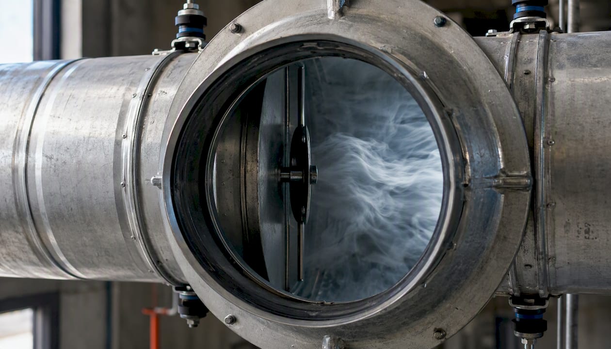
Structureborne (vibrational) noise travels through the building structure itself, rigid duct hangers, unisolated piping, or a fan base bolted directly to a slab, and reradiates as sound somewhere far from the actual source. It is the hardest to diagnose because the audible complaint location rarely matches the vibration source, and it tends to concentrate in the lowest frequency bands, often below 63 Hz.
| What You Hear | Likely Cause | First Action |
|---|---|---|
| Steady low hum or whine at fan speed | Mechanical (motor/fan imbalance) | Check bearing lubrication and fan balance |
| Rushing or hissing at diffusers | Airflow/ductborne (high velocity) | Measure duct velocity, inspect damper position |
| Rumble felt through floor or walls | Structureborne vibration | Inspect isolators and flanking rigid connections |
| Rattle that varies with wind or cycling | Loose panel or flex connector | Tighten fasteners, inspect flex connector condition |
| Tonal whistle at grilles | Airflow (undersized outlet, sharp edges) | Check face velocity against manufacturer data |
A quick statistic worth internalizing: rooftop air handling unit installations that add horizontal discharge, adequate plenum volume, and dual-wall round ducts at the discharge point can eliminate persistent low-frequency rumble that would otherwise require an expensive retrofit. That is a design decision made once, at almost no incremental cost, versus a structural fix made after tenants complain.
How Do You Measure and Diagnose HVAC Noise Problems?
A defensible field assessment requires the right instruments and a repeatable protocol, not a guess based on how annoying the sound feels standing in the room.
Instrumentation you need:
- A Type 1 or Type 2 sound level meter with octave-band or one-third octave-band analysis capability.
- A contact accelerometer for structureborne vibration measurement at isolators, hangers, and equipment bases.
- A tachometer to confirm actual fan or motor RPM against nameplate and design speed.
- An airflow hood or pitot tube traverse kit with a manometer to verify actual duct velocity and static pressure against design values.
Measurement checklist:
- Take a source measurement close to the equipment (fan discharge, compressor casing) to establish a baseline spectrum.
- Measure at duct inlet and outlet locations on either side of any silencer or lining to calculate installed insertion loss.
- Take receiver measurements at the occupied space, typically 1.2 to 1.5 meters above the floor, away from reflective surfaces.
- Use the accelerometer at isolator mounts and any suspected flanking path (rigid pipe, conduit, structural bracket).
Protocol notes worth following every time: measure for a minimum of 30 to 60 seconds per location to capture a stable average, and always subtract background noise levels measured with the HVAC system off if the two levels are within 10 dB of each other. Check for tonality, a pure-tone component that stands out from the broadband spectrum, since tonal noise is penalized more heavily in most acceptance criteria and is far more noticeable to occupants than broadband hiss at the same overall decibel level. Compare the resulting octave-band spectrum against the applicable NC curve for the space type; use A-weighted overall levels for a quick pass/fail screen, but always fall back to octave-band data when troubleshooting, because two spaces with identical A-weighted readings can have completely different occupant complaints depending on where the energy sits in the spectrum.
What Mitigation Methods Work for Each Noise Path?
Every mitigation option belongs to one of the three paths, and picking the wrong category wastes budget without fixing the complaint.
Source controls start at equipment selection. Choosing a fan or compressor that operates near its peak efficiency point, rather than a smaller, cheaper unit running near its capacity limit, cuts generated noise before any acoustic treatment is even considered. Variable frequency drives (VFDs) paired with soft-start strategies reduce the acoustic spike that occurs at full-speed startup, and routine motor and fan-wheel balancing prevents the tonal whine that develops as bearings wear.
Air-path treatments address noise traveling through the ductwork:
- Rectangular duct silencers work well in straight duct runs with moderate space constraints and are the most common general-purpose choice.
- Elbow silencers combine attenuation with a direction change, useful where duct routing is tight and a separate straight silencer will not fit.
- Circular silencers suit round duct systems and rooftop unit connections where rectangular hardware is impractical.
- Duct lining (fiberglass or foam) adds broadband high-frequency absorption but contributes negligible low-frequency control and can raise indoor air quality concerns if not properly encapsulated.
- Acoustic plenums use volume and absorptive surfaces to attenuate noise at equipment room boundaries.
- Acoustic louvers control noise breakout at building envelope penetrations, such as outdoor air intakes near occupied windows.
Each of these carries a trade-off: more attenuation generally means more pressure drop and, past a certain airflow velocity, the silencer itself starts generating self-noise that partially offsets the benefit it was installed to provide.
Structureborne measures stop vibration before it reaches the building structure. Spring isolators handle low-frequency, heavy equipment like chillers and large air handling units; rubber-in-shear isolators suit lighter fans and pumps with higher disturbing frequencies. Flexible connectors at fan inlets and discharges, and at pump suction and discharge, prevent vibration from bypassing the isolators through rigid ductwork or piping. Inertia bases, a concrete mass poured under the equipment and mounted on isolators, add stability for large rotating machinery and reduce rocking motion that lighter isolator-only mounts cannot control. Isolation hangers for suspended ductwork and piping need a static deflection appropriate to the disturbing frequency; a common rule of thumb calls for the isolator’s natural frequency to sit below one-third of the disturbing frequency to achieve roughly 90 percent isolation efficiency.
Installation rules that get skipped too often:
- Maintain clearance around silencers and enclosures; airtight, cramped installations create their own turbulence.
- Never let rigid conduit, pipe, or structural bracing bypass a vibration isolator, since one flanking path can defeat an otherwise correctly specified isolation system.
- Stage silencers a reasonable distance downstream of the fan discharge rather than immediately at the outlet, reducing the regenerated turbulence noise that occurs when a silencer sits inside a highly turbulent airstream.
Pro Tip: Always test for generated noise separately from insertion loss once a silencer is installed. A silencer can show excellent lab-rated insertion loss and still make a duct noisier overall if the installed airflow velocity exceeds the velocity used in its test rating. Confirm actual field velocity against the manufacturer’s tested condition before assuming the catalog number will hold.
How Do You Select the Right Silencer, Lining, or Isolator?
Vendor catalog numbers only mean something when they are tested under conditions that match your installation. The three metrics that matter for air-path components are insertion loss by octave band, generated noise, and pressure drop, and AMCA’s guidance on air-system noise treats all three as interdependent rather than as separate line items to optimize independently. A silencer with high insertion loss at high airflow will often also generate more self-noise and impose a steeper pressure drop, so selection is always a three-way compromise, not a single-metric shopping exercise.
Selection checklist:
- Define the required insertion-loss profile by octave band, not a single dB(A) number, since a silencer that performs well at 1,000 Hz can be nearly useless at 125 Hz.
- Set an acceptable pressure-drop ceiling before shopping catalogs, and confirm the fan static pressure budget can absorb it without derating airflow.
- Check physical length and open-area percentage against available duct space; higher open-area silencers generally cost more insertion loss for the same length.
- Reference the test standard the manufacturer used, ideally ASTM E477, so the numbers in the submittal are comparable across vendors.
For sound transmission through walls and partitions around mechanical rooms, Sound Transmission Class (STC) and Outdoor Indoor Transmission Class (OITC) ratings apply, with OITC being the more relevant metric for exterior noise sources like rooftop units near operable windows.
| Component Type | Typical Strength | Typical Trade-off |
|---|---|---|
| Rectangular duct silencer | Strong mid/high-frequency insertion loss | Pressure drop rises sharply above rated velocity |
| Elbow silencer | Space-saving, moderate attenuation | Lower insertion loss than an equivalent straight unit |
| Acoustic duct lining | Good broadband high-frequency absorption | Minimal low-frequency benefit; IAQ considerations |
| Acoustic louver | Controls envelope breakout noise | Adds resistance that must be included in airflow calculations |
| Spring isolator | Best for low-frequency, heavy equipment | Requires more installed height and careful leveling |
| Rubber-in-shear isolator | Simple, low-cost, compact | Less effective for very low disturbing frequencies |
Always account for the gap between catalog performance and installed performance, commonly called the “system effect.” A silencer tested in a straight, unobstructed duct section in a lab will rarely deliver identical performance immediately downstream of an elbow or a fan discharge in the field. When the actual system-effect penalty is unknown, a conservative allowance of an added few dB of expected performance loss, confirmed by field measurement after installation, prevents an unpleasant surprise at commissioning.
Where Should Silencers and Isolation Be Placed for Best Performance?
Component selection only pays off if placement preserves the aerodynamic and structural conditions the performance data assumed. Silencers and isolators installed against manufacturer clearance recommendations routinely underperform their rated numbers, sometimes badly.
Clearance guidance that protects installed performance:
- Keep branch duct takeoffs 4 to 5 duct diameters apart under normal conditions, extending to 10 diameters for high-velocity systems, since closely spaced takeoffs create competing turbulence zones that generate flow noise independent of duct lining.
- Give silencers straight duct runs on both sides where possible; installing one directly at a fan discharge or immediately before a sharp turn invites regenerated turbulence noise that erodes the rated insertion loss.
- Size air handling unit room and mechanical plenum spacing to allow adequate distance between the fan and any wall penetration, reducing direct sound transmission through thin partitions.
- Use flow straighteners or honeycomb grids rather than protruding turning vanes at abrupt transitions, since honeycomb grids reduce turbulence more predictably than sharp-edged extractors.
A practical clearance and transition sequence for new designs:
- Confirm fan selection operates near peak static efficiency at design airflow before finalizing duct sizing.
- Locate the first branch takeoff at least 4 to 5 diameters downstream of the fan discharge or any elbow.
- Insert silencers in a straight section with manufacturer-recommended upstream and downstream clearance, not immediately adjacent to a fitting.
- Verify diffuser face velocity against manufacturer noise-rating data before finalizing terminal selection.
- Confirm isolator selection accounts for total equipment weight distribution, not just an average per-mount load.
When the actual system-effect penalty cannot be calculated with confidence at design stage, carry a conservative pressure-drop allowance in the fan selection and verify it against field measurements during commissioning rather than assuming the catalog curve will hold exactly.
Which Codes and Standards Govern HVAC Noise Control?
Specifications that cite recognized standards give both the engineer and the property manager an enforceable, measurable benchmark instead of a subjective “too loud” complaint with no resolution path.
The relevant references for Canadian projects include ASHRAE’s source–path–receiver guidance in the ASHRAE Handbook, Chapter 49, which remains the primary technical reference cited in Canadian mechanical specifications for noise and vibration control. ASTM E477 governs duct silencer testing for insertion loss, airflow generated noise, and pressure drop, and ASTM E413 provides the standard method for computing sound transmission class ratings used for partition and enclosure performance. Provincial building codes, following the general intent of the National Building Code framework, require designers to limit occupant exposure to unacceptable mechanical sound levels, particularly in residential and health-care occupancies where sleep and recovery spaces demand stricter acceptance criteria.
A defensible design workflow moves through these stages:
- Preliminary equipment selection using manufacturer sound-power data at the actual operating point, not a generic nameplate figure.
- Path specification, silencers, lining, isolation, written into the contract documents with named test standards.
- Shop drawing review confirming submitted equipment matches the specified performance and physical constraints.
- Commissioning with acoustical verification, comparing measured field performance against the NC or dB(A) criteria stated in the specification.
Professional Engineers Ontario’s acoustical guideline is explicit that a licensed engineering practitioner (LEP) should be engaged for acoustical due diligence, mitigation design, and field verification whenever noise affects occupant health, land-use compatibility, or code compliance. That is not a discretionary nicety on complex projects, it is the professional standard the guideline sets for anyone stamping drawings that touch noise-sensitive design.
Where noise impacts land use or occupant health, competent engineering oversight is not optional. It is the professional standard the work is measured against.
What Belongs in a Noise-Control Spec and Commissioning Plan?
A specification without measurable acceptance criteria is not enforceable, and a commissioning plan without a documented baseline cannot prove anything improved.
Spec checklist items to include on every project:
- Required insertion loss by octave band for every silencer, referenced to a named test standard.
- A maximum allowable pressure drop across each path treatment at design airflow.
- The specific test standards the manufacturer must have used, with independent third-party test data required rather than manufacturer self-certification alone.
- Warranty terms covering acoustic performance degradation, not just mechanical failure.
- A maintenance clause specifying inspection intervals for liner condition and isolator integrity.
Commissioning test sequence:
- Take baseline pre-installation measurements at the receiver location if the space is occupied or partially built out before mechanical work begins.
- Measure installed-condition sound levels at the same receiver locations once equipment is running at design airflow.
- Verify vibration isolation performance with an accelerometer at each isolator mount, confirming static deflection matches the design value under actual load.
- Conduct a duct breakout test at sensitive locations, checking whether duct wall vibration is radiating noise directly through thin sheet metal into an adjacent occupied space.
Maintenance items that preserve acoustic performance over time:
- Inspect duct liner condition annually for erosion, moisture damage, or delamination that reduces absorption.
- Re-torque or re-level isolator mounts on a scheduled cycle, since settling and thermal cycling loosen many isolator types over a few years.
- Rebalance fan wheels periodically, particularly on systems with heavy seasonal dust loading that can create rotating imbalance over time.
What Are the Quick Fixes When Tenants Complain About HVAC Noise?
Start with a short diagnostic flow before reaching for tools: is the noise constant or intermittent? Does it correlate with equipment cycling on and off, or does it change when a damper or valve opens? A complaint that only appears during heating mode, for instance, often points to a specific damper actuator or a duct section that expands and contacts a structural member as it heats up.
Quick-fix options worth trying before a full redesign:
- Inspect and replace any cracked or loose flexible connectors at fan inlets and discharges.
- Rebalance ducts if a recent renovation changed airflow distribution without updating dampers accordingly.
- Add temporary sound blankets around an accessible mechanical unit as a stopgap while a permanent silencer is sourced.
- Install a small silencer in the specific branch run serving the complaint area rather than treating the entire system.
- Tighten and re-inspect equipment mounts and isolator hardware that may have loosened over time.
Risk caveats worth taking seriously: adding lining or a silencer to fix one complaint can raise system pressure drop enough to push the fan into a less efficient, noisier operating point elsewhere on the curve. A quick fix applied without checking the fan’s total static pressure budget can trade one noise complaint for a new one down the duct run. Field reports consistently show that retrofit noise-control failures often result from correct products installed without system-level integration, which is exactly the trap a rushed quick fix can fall into.
Pro Tip: Before installing any retrofit silencer, measure actual duct velocity at that location first. A silencer sized for a catalog’s rated velocity will generate more noise than it removes if the actual field velocity runs meaningfully higher, which happens more often than most retrofit crews expect on older systems that have been rebalanced multiple times without updating the drawings.
When Should You Bring In an Acoustical or MEP Engineer?
Certain red flags mean a DIY fix or a maintenance-team retrofit is the wrong tool for the job. Low-frequency rumble that persists below NC-30 in an occupied space, complaints affecting health-critical spaces like patient rooms or recording studios, or any noise issue with regulatory or land-use exposure (residential development near an existing rooftop unit, for example) all warrant bringing in a qualified engineer rather than iterating with sound blankets.
A structured engagement typically follows this sequence:
- Site survey to gather baseline conditions, equipment nameplate data, and occupant complaint history.
- Measurement report documenting octave-band spectra at source, path, and receiver locations against the applicable NC criteria.
- Concept mitigation options presented with cost and performance trade-offs, so the property manager can make an informed budget decision rather than approving a single unexplained line item.
- Final design and specification with named test standards, insertion-loss requirements, and pressure-drop limits written into the contract documents.
- Shop drawing review to confirm submitted equipment actually meets the specified performance before it is installed.
- Commissioning verification with a before-and-after measurement comparison and a formal acceptance statement.
Deliverables from a properly scoped engagement should include a measurement report with real octave-band spectra (not just a single A-weighted number), complete specification text ready for bidding, installation drawings showing clearances and isolator locations, and a commissioning report documenting measured performance against the original design criteria. Property managers evaluating HVAC design services should expect nothing less than this full documentation trail, since a verbal assurance that “it’s been fixed” carries no evidentiary weight if the complaint returns.
Where Noise Control Projects Actually Go Wrong
The mistake I see repeated most often on failed retrofits is treating each acoustic component as an isolated purchase rather than a system decision. An engineer specifies a silencer with excellent lab-rated insertion loss, a contractor installs it two duct diameters from a 90-degree elbow because that is where the ceiling space happened to be open, and the finished installation delivers a fraction of its rated performance. Nobody did anything technically wrong in isolation. The failure was in the gap between the parts, exactly where system effects live and where nobody was assigned to check.
A second recurring error is ignoring flanking paths on vibration isolation. A design calls for spring isolators under a rooftop unit, the isolators get installed correctly, and the unit still transmits a low-frequency hum into the floor below because the refrigerant piping runs in rigid conduit clamped directly to structural steel the whole way down. The isolators were never the problem. The rigid pipe bypassing them was, and it went unnoticed because the commissioning checklist only tested the isolator mounts themselves, not the piping that ran straight past them.
The corrective action in both cases is the same: verify installed conditions against the design intent with a tape measure and an accelerometer, not a visual sign-off from a distance. Noise control succeeds or fails on details most trade drawings never show clearly enough for a contractor to catch on their own.
How Futuregenconsulting Supports HVAC Noise Control Projects
Futuregenconsulting is the direct alternative to hiring a generalist contractor for HVAC noise problems: rather than a retrofit crew guessing at fixes with sound blankets and hoping the complaint goes away, you get an MEP engineering firm that measures, specifies, and verifies performance against named standards from the start.

Futuregenconsulting’s HVAC engineering team supports noise-control projects at whatever stage they enter, whether that is a spot measurement to diagnose a single tenant complaint, a full acoustical study for a new build, specification support to get insertion-loss and pressure-drop language into your contract documents correctly, or commissioning and field verification once equipment is installed. The firm’s HVAC system design services cover the full path from equipment selection through construction-ready, engineer-stamped drawings, built around the same source–path–receiver framework this article has walked through. For developers, contractors, and property managers in Ontario and Alberta dealing with a persistent noise complaint or planning a new mechanical system, the next step is requesting a proposal through Futuregenconsulting’s MEP engineering services page to scope a measurement visit or a full specification package before the next tenant complaint lands on your desk.
Frequently Asked Questions About HVAC Noise Control
What is the fastest way to tell if HVAC noise is mechanical or airflow-related?
Walk the duct run while the system operates. Mechanical noise stays roughly constant in level as you move away from the equipment; airflow noise gets noticeably louder near elbows, dampers, or undersized takeoffs regardless of distance from the fan.
What NC rating should an office or residential bedroom target?
Most offices target NC-30 to NC-40, while bedrooms and boardrooms typically need NC-25 or lower given their higher sensitivity to background noise.
Does adding duct lining fix low-frequency rumble?
Rarely. Duct lining is effective for broadband, high-frequency absorption but contributes little to low-frequency mechanical or structureborne noise, which usually needs vibration isolation or a source-side fix instead.
How much does noise control typically add to an HVAC project budget?
Addressing noise control at the design stage typically adds 1 to 2 percent of total HVAC system cost, while correcting the same issue after installation usually costs significantly more.
When does a noise complaint require a licensed engineer instead of an in-house fix?
Escalate when the noise is low-frequency rumble below NC-30, affects health-critical or noise-sensitive spaces, or carries regulatory or land-use exposure, situations where PEO’s acoustical guideline expects professional engineering involvement.
Sources
Cite these directly in specifications and acceptance-test documentation rather than paraphrasing them secondhand:
- ASHRAE Handbook, Chapter 49: Noise and vibration control
- Understanding & reducing air-system noise (AMCA resource)
- A Practical Guide to Noise and Vibration Control for HVAC Systems (ASHRAE excerpt)
- Acoustical guideline — Professional Engineers Ontario
Building these references directly into acceptance criteria, rather than leaving performance requirements vague, is what turns a noise-control spec from a wish list into an enforceable contract document.