
Effective harmonic mitigation design starts with measurement, not equipment. Verify the harmonic spectrum against IEEE 519 and Canadian compatibility guidance, then apply targeted passive filters to dominant orders such as the 5th and 7th. Specify active or hybrid solutions when load variability or a wideband spectrum demands dynamic compensation. Confirm the result with post-installation measurements.
TL;DR:
- Hydro One cites 8% long term voltage THD at low voltage; confirm your PCC voltage class before setting targets, since transmission limits tighten.
- Log at least one full operating cycle, including startup and generator operation, and compare voltage THD with capacitor banks switched both in and out.
- For variable frequency drives, use terminal current THD below 5% at rated load as a screening trigger, then verify utility limits at the PCC.
- For fixed dominant orders such as the 5th and 7th, use passive branches tuned below each target, then check frequency response for resonance.
- For mixed loads, passive branches can remove dominant harmonics while a smaller active unit handles residual and variable current, limiting active capacity and losses.
Table of Contents
- Why harmonics matter and which standards to design against
- Assessing the site: measurement, data collection, and verification before design
- Passive filter design fundamentals: single-tuned, high-pass, and C-type
- Active and hybrid solutions: when to specify them and how they work
- How to choose: practical selection criteria and decision checklist
- Step-by-step design procedure from impedance assessment to final tuning
- Implementation considerations: resonance, interactions, protection and maintenance
- A practical example and how we approach these projects
- What seasoned engineers should watch for
- How our power system studies and distribution design support your project
- FAQ
- Sources
Why harmonics matter and which standards to design against
Harmonics are currents and voltages at integer multiples of the fundamental frequency, produced mainly by rectifiers, variable frequency drives, UPS systems and LED or switch-mode power supplies. Three terms drive every design decision:
- Individual harmonic order: the magnitude of a single harmonic (5th, 7th, 11th and so on), expressed as a percentage of the fundamental or of the demand current.
- THD (total harmonic distortion): the combined distortion of a voltage or current waveform relative to its own fundamental at that instant.
- TDD (total demand distortion): current distortion referenced to the maximum demand load current rather than the instantaneous fundamental, which makes it the fairer metric for a lightly loaded feeder.
Voltage distortion is the number that affects neighboring customers, while current distortion is what your facility injects. Design objectives should therefore be stated at the point of common coupling (PCC): voltage THD and individual voltage limits for the bus, and current TDD limits for what the installation injects into the utility. IEEE Std 519 (2014) and CAN/CSA-C61000-2-2:04 provide the individual harmonic voltage limits and THD targets that serve as design criteria, and the Hydro One power quality reference summarizes them, including a long-term voltage THD limit of 8% at low voltage. Transmission-level limits tighten as bus voltage rises, so confirm the limit for your own PCC voltage class before writing a target.
Where a design involves drives, equipment guidance gives a practical anchor. Natural Resources Canada notes that variable frequency drives typically meet harmonic requirements when current total harmonic distortion at the terminals stays below 5% at rated load.
Rule of thumb from the source: keep drive terminal current THD below 5% at rated load. Treat it as a screening trigger, then check the PCC against the utility’s limits.
For Canadian projects, tie the electrical design to the Canadian Electrical Code (CSA C22.1) and, in Ontario, the Ontario Electrical Safety Code, and confirm any utility-specific interconnection or power quality requirements early.
Assessing the site: measurement, data collection, and verification before design
A filter sized from nameplate data is a guess. Measure first, and measure long enough to catch every operating state.
Equipment. Use a Class A power quality analyzer or power harmonic analyzer capable of recording voltage and current harmonics, with synchronized three-phase capture. Current transformers or flexible Rogowski coils should suit the expected current range. Natural Resources Canada guidance for drive installations likewise tells practitioners to confirm harmonic levels with power harmonic analyzers before committing to mitigation.
Capture duration. A single spot reading misses duty cycles. Record at least one full operating cycle of the facility, and for commercial and industrial sites, continuous logging across the facility’s operating patterns can capture weekday, weekend and shift variation. Add a short high-resolution capture during startup, load transfers and generator operation.
What to record, in order:
- Current harmonic spectrum per phase at the suspected source and at the PCC, including individual orders and TDD.
- Voltage THD and individual voltage harmonics at the PCC and at sensitive buses.
- Short-circuit level and source impedance at the PCC, from the utility or from a short-circuit study.
- Load duty cycles, including which drives, rectifiers or chargers run together.
- Existing capacitor banks, their kvar rating and switching steps.
- Fundamental power factor and demand profile.
Where voltage distortion at the PCC approaches the applicable IEEE 519 limit, or where capacitor banks are present alongside non-linear load, run a full harmonic study rather than relying on rules of thumb. The study should cover impedance versus frequency as seen from the harmonic source, because that is where resonance hides. Our power system studies cover the short-circuit and source impedance modeling that this step depends on.
Pro Tip: Log with the capacitor banks both in and out of service. The difference in voltage THD tells you more about resonance risk than any single snapshot.
Passive filter design fundamentals: single-tuned, high-pass, and C-type
Passive filters trap harmonic currents in LC circuits tuned near the offending harmonic order, most commonly the 5th and 7th, as described in a Université du Québec thesis. They remain common for high-power and medium-voltage applications because of lower upfront cost and simplicity, as Hydro One’s power quality definitions note, but they are fixed in behavior and can interact with the system.
Topologies and where each fits:
- Single-tuned: a series L and C tuned to one order. The first choice for a dominant 5th, 7th or 11th, with low loss and straightforward sizing. A 5th-order filter on a six-pulse rectifier bus is the classic case.
- High-pass (second-order damped): adds a damping resistor so a single branch attenuates everything above a corner frequency. It suits a broad residual spectrum above the 11th, at the cost of resistor losses at the fundamental.
- C-type: a high-pass variant whose extra capacitor blocks fundamental current through the damping resistor, cutting losses substantially. It gives wideband damping with better efficiency, and it is useful when a lower-order resonance must be damped.
Tuning frequency and Q. Never tune exactly on the target harmonic. Component tolerance, capacitor aging, temperature drift and changes in system impedance all shift the real resonance, and a filter that drifts above the harmonic order can move the parallel resonance onto it. Academic passive filter designs, such as this study of passive filters for rectifiers, stress selecting the Q factor and tuning frequency while accounting for parameter variation and manufacturing tolerances.
A higher Q gives a sharper, deeper notch but a narrower effective band and greater sensitivity to detuning. A lower Q is more forgiving and damps resonance better, but it passes more residual current. As a design habit, choose a moderate Q for sites with changing impedance and reserve high Q for stable, fixed-load installations.
Sizing L and C. Start from the reactive power the filter must supply at the fundamental, which doubles as power factor correction. Select the capacitor for that kvar at the system voltage, then derive the reactor from the tuning order. Check capacitor voltage and current stress, since series tuning raises voltage across the capacitor above the bus value.
Resonance risk. A capacitor bank or filter forms a parallel resonance with source inductance. If that resonance lands near a harmonic present in the load current, harmonics are amplified rather than reduced. Poorly sized filters are the textbook way to turn a marginal harmonic problem into a damaging one. Mitigate by running an impedance sweep, adding detuning reactors to existing banks, staging filter branches from lowest order upward, or choosing a damped topology.
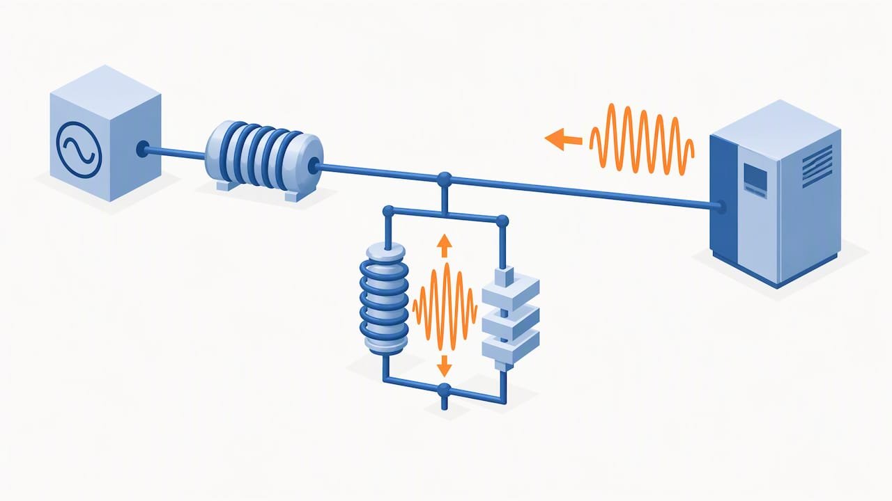
Takeaway: always tune below the target order and verify the margin against component tolerance.
Active and hybrid solutions: when to specify them and how they work
Active filters use power electronics to measure the load current and inject a cancelling current, which gives them adaptability that a fixed LC network lacks. Review literature, including a review of active harmonic mitigation, shows parallel active power filters and active front end drives growing in popularity, with manufacturer literature noting both capabilities and caveats.
Topologies.
- Shunt active power filter: connected in parallel at the load or PCC, it injects compensating harmonic current. This is the workhorse for current harmonics, and it can often also correct reactive power and balance phases.
- Series active filter: inserted in series through a coupling transformer to isolate voltage distortion between the source and a sensitive load. Better suited to protecting a critical load from supply-side voltage harmonics.
- Active front end drives: the mitigation is built into the converter itself, which suits new drive installations rather than retrofits.
Control algorithms. Performance depends strongly on the control method, as the Hydro One PQ reference guide points out, with examples including the synchronous reference frame, Kalman filtering and instantaneous power theory. In practice, the synchronous reference frame method separates the fundamental from harmonics in a rotating frame and is widely used for its clear structure. Instantaneous power theory computes reference currents from power quantities and responds quickly. Ask any vendor which algorithm is used, how it behaves under unbalance and distorted supply voltage, and what its response time is.
When active is the right call:
- Dynamic loads whose harmonic spectrum changes with operating state.
- Scattered harmonic sources where one fixed tuned branch cannot cover the spectrum.
- Rapid load change, such as EV charger clusters or cycling drives.
- Sites where resonance with existing capacitor banks makes passive filters risky.
The hybrid approach. Combining passive bulk filtering with active fine compensation often gives the better economic and technical trade-off for complex installations, as a paper on hybrid filters concludes. The passive branch removes the dominant orders and supplies fundamental reactive power cheaply, while a smaller active unit handles the residual and the variable portion. The active device can be rated for a fraction of the total harmonic current, which keeps cost and losses down, and it can damp passive filter resonance dynamically.
How to choose: practical selection criteria and decision checklist
Selection should follow site data, not vendor preference. Work through these questions in order:
- Spectrum shape: a few dominant tones points to passive; a broad or shifting spectrum points to active or hybrid.
- Load variability: steady loads suit fixed filters; variable loads favor active compensation.
- Source impedance: a weak source amplifies voltage distortion and raises resonance risk, which pushes toward damped or active solutions.
- Cost: passive has lower capital cost; active costs more upfront but may avoid redesign when loads change.
- Space and cooling: reactors and capacitor enclosures are bulky; active units are compact but need ventilation.
- Maintenance: passive needs capacitor health checks; active needs firmware, fan and power-module care.
- Future expansion: a design that cannot absorb added non-linear load will be re-engineered, so size margin in early.
Common project archetypes:
- Fixed large six-pulse drives or rectifiers: targeted single-tuned passive filters, usually 5th and 7th.
- Variable non-linear load farms, such as mixed drive plants or EV charging hubs: hybrid or active.
- Sensitive process loads on a distorted supply: series active or isolation.
- Existing facility with capacitor banks and rising harmonics: impedance study first, then detuned banks or active compensation.
Specification advice. Write performance-based specifications: state the PCC limits in IEEE 519 terms, the measurement method and the acceptance test, rather than naming a topology or brand. Industry roadmaps note that a lack of standardized specifications across utilities hinders projects and recommend flexible, performance-based specifications to avoid single-vendor lock-in, as this grid technology roadmap observes.
Pro Tip: Require bidders to submit their harmonic simulation results alongside the equipment price. It exposes unsupported performance claims before purchase.
Step-by-step design procedure from impedance assessment to final tuning
Follow this workflow to produce a validated design and commission it.
-
Run the baseline measurement campaign and define load states. Capture the spectrum, voltage THD, TDD and demand at the PCC and at the main sources, as set out in the assessment section. Define discrete load states (minimum, typical, peak, generator operation) so every later calculation references real operating points rather than an average.
-
Estimate short-circuit level and source impedance. Obtain the fault level from the utility or calculate it from the service transformer and upstream data. Build a frequency-dependent model of the network, including transformer leakage reactance, cable capacitance, and every capacitor bank. For harmonic flow, model the source as an impedance rising with frequency, and note that the model is only as good as its inputs, which is why measured data should calibrate it. Our power system studies include this modeling.
-
Select a preliminary topology and size it. From the measured spectrum, pick passive, active or hybrid using the selection checklist. For a passive branch, calculate the capacitor from the required fundamental kvar, derive the reactor from the tuning order with the margin below the target harmonic, choose Q for the expected impedance variation, and compute capacitor voltage and current stress. For an active unit, size the rated compensation current to cover the worst-case harmonic current plus margin, and check the maximum injection against the load’s peak spectrum.
-
Simulate. Run a steady-state harmonic flow study for each load state, sweeping impedance versus frequency at the PCC to find parallel resonances. Add electromagnetic transient (EMT) simulation where switching events, inrush or active filter control interaction matter. Then test sensitivity: vary capacitance and inductance for tolerance and aging, vary source impedance for system changes, and add or remove capacitor stages. A design that only works at nominal values is not finished.
-
Coordinate protection and commission. Verify that fuses, breakers and relays coordinate with filter inrush and harmonic current, including capacitor switching transients. Specify point-on-wave switching or pre-insertion where inrush is severe. Set protection for overload, unbalance and overtemperature. At commissioning, repeat the baseline measurements with the filter energized across every defined load state and compare against the PCC limits. Only a measured result closes the design.
-
Document and hand over. Record as-built tuning, measured results, alarm setpoints and the recommended re-measurement interval. This record is what a utility will ask for if a complaint arises.
Where the project interfaces with a generator or utility connection, expect the utility to require studies and models. Hydro One’s generator interconnection requirements state that interconnecting facilities must not cause excessive harmonics and must comply with IEEE 519 and other regional power quality requirements. Staged builds raise a related issue: temporary power and load transfers during commissioning can briefly change the source impedance, and a guide to temporary power for data center builds is a useful reference when planning those transitions.
Implementation considerations: resonance, interactions, protection and maintenance
A sound design can still fail in the field. These are the issues that most often undermine it.
- Resonance diagnosis. If voltage THD rises after a capacitor or filter is added, suspect a parallel resonance. An impedance sweep from the harmonic source’s point of view, in the model and by field measurement, locates it. Mitigate with detuning reactors, damped filter branches, shifting the tuning order, or adding active damping.
- Capacitor bank interaction. Power factor correction banks and harmonic filters share the same network. Banks that were harmless before new non-linear load arrived can become amplifiers. Coordinate any change with the existing correction equipment, and see our notes on power factor correction for industrial facilities when banks and filters must work together.
- Protection and thermal limits. Reactors, capacitors and damping resistors run warm. Verify enclosure ventilation, ambient temperature rating, and capacitor overvoltage and overcurrent withstand under worst-case distortion.
- Environment. Indoor versus outdoor siting, cold-weather starting and moisture affect component life and should be specified.
- Maintenance and monitoring. Schedule capacitor capacitance checks, torque verification, infrared scans and fan inspection. Fit permanent power quality monitoring at the PCC so drift is caught before it becomes a limit violation.
- Acceptance measurements. Prove compliance with a post-installation campaign across all load states, reporting voltage THD, individual orders and TDD against the agreed limits.
Pro Tip: Set a trend alarm on voltage THD at the PCC at a level comfortably below the limit. Slow capacitor degradation shows up as drift long before it shows up as a failure.
A practical example and how we approach these projects
Consider an anonymized industrial building with several large variable frequency drives and an existing automatic power factor correction bank. Field logging showed the dominant current components at the 5th and 7th orders, with voltage THD rising whenever the capacitor bank stepped in, which pointed to a parallel resonance near the 5th. The load was largely fixed during production hours but with a smaller, cycling portion.
A design response can follow the workflow above. Model source impedance and the bank, confirm resonance in simulation, and consider detuned single-tuned branches for the 5th and 7th, with the tuning margin set below each order. For a cycling portion, a smaller active unit can be added as a hybrid compensation stage. Post-installation measurement across all load states can serve as the acceptance test.
Design for the measured spectrum, tune below the target order, and let the commissioning measurements, not the model, declare the job complete.
This is the same measurement-driven logic that IEEE 519 compliance expects. We are a Canadian engineering firm with experience in electrical and mechanical design, and our power system studies and power distribution design cover the short-circuit modeling, specification and construction review that a harmonic mitigation project depends on.
What seasoned engineers should watch for
In my view, the most common mistake is trusting the model over the meter. A harmonic study built on assumed impedance and nameplate spectra can look convincing and still be wrong, so I would rather see a modest design verified by measurement than an elegant one that was never checked. Prioritize measured data and model validation first.
Second, buy performance, not products. Write the PCC limits and the site acceptance test into the specification, and make payment depend on passing it. Third, bring in an engineering consultant early when capacitor banks, weak sources or mixed drive and charger loads are involved, because that is where resonance surprises cost the most to fix.
— Sanjay
How our power system studies and distribution design support your project

When you need delivered engineering rather than guidance, we can take the work from measurement to commissioning. Our power system studies and power distribution design services are the most relevant to harmonic mitigation projects.
- Measurement campaigns and load-state definition at the PCC and major sources.
- Modeled short-circuit, source impedance and harmonic studies with resonance screening.
- Filter topology selection, sizing and performance-based specifications.
- Engineer-stamped deliverables and construction documentation that carry the mitigation into the distribution design.
- Construction review and commissioning support, including acceptance measurements.
We design to the codes that apply to your project and your utility’s power quality requirements. To discuss your site, contact us through our power system studies page and tell us about your loads, your PCC and the limits you need to meet. Current pricing details are on our website.
FAQ
What are the disadvantages of using an active harmonic filter?
Active filters generally cost more upfront than passive filters and contain power electronics that need cooling, firmware management and periodic service. Their performance also depends strongly on the control algorithm, so vendor selection and commissioning matter, as the Hydro One PQ reference guide indicates.
What is the purpose of a harmonic filter in a VFD?
It reduces the harmonic current the drive’s rectifier injects into the supply so that distortion at the terminals and PCC stays within limits. Natural Resources Canada notes that drives typically meet harmonic requirements when current THD at the terminals stays below 5% at rated load.
How do harmonics affect power factor?
Harmonic currents add distortion without delivering useful power, so true power factor falls below displacement power factor even when the fundamental is well corrected. They can also push correction capacitors into resonance, which amplifies distortion rather than improving the system, a risk Hydro One’s power quality definitions describe for poorly sized capacitor banks.
How does a passive harmonic filter work?
A passive filter is an LC circuit tuned slightly below a target harmonic order, giving that harmonic a low-impedance path so the current is shunted away from the source. A thesis from the Université du Québec describes such filters as less flexible than active filters, with a possibility of causing resonance if poorly matched to the system.