

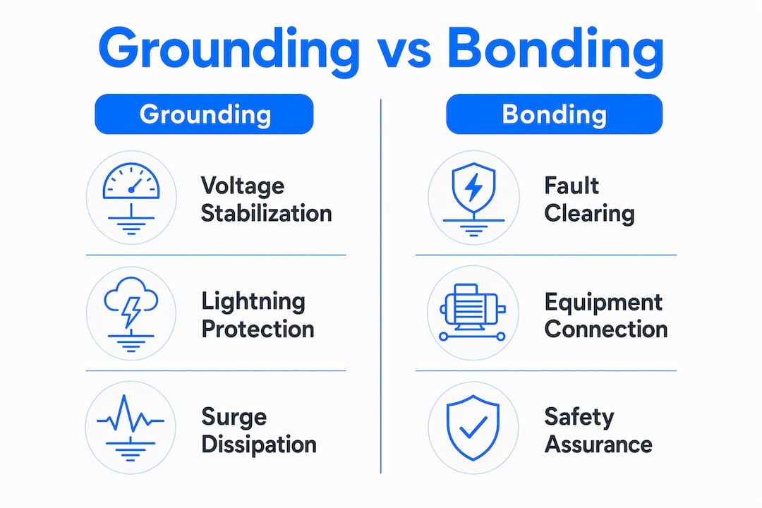
Grounding and bonding are defined as two distinct but complementary electrical safety functions required under NEC Article 250. Grounding connects the electrical system to earth to stabilize voltage and dissipate lightning surges. Bonding connects all metallic components together to create a low-impedance fault current path that trips overcurrent devices. Electricians and engineers in Alberta working on projects governed by the Canadian Electrical Code must understand that bonding clears faults; grounding does not. Confusing these two functions produces installations that pass visual inspection but fail catastrophically under fault conditions.
What are the electrical and safety functions of grounding and bonding?
Grounding stabilizes system voltage and provides a path for lightning and surge energy to dissipate into the earth. It does not, however, clear ground faults. Earth has high impedance, which means fault current flowing through earth cannot reach the level needed to trip a breaker or blow a fuse.
Bonding performs the critical safety function that grounding cannot. When a phase conductor contacts a metal enclosure, bonding conductors carry that fault current back to the source along a low-impedance path. The resulting high current magnitude operates the overcurrent device within milliseconds, removing the hazard.
NEC 250.4(A) separates these functions explicitly:
- NEC 250.4(A)(1): Grounding of electrical systems stabilizes voltage to earth during normal operation and lightning events.
- NEC 250.4(A)(3): Grounding of conductive materials limits voltage imposed by lightning and line surges.
- NEC 250.4(A)(5): Effective ground-fault current paths must be permanent, electrically continuous, and capable of carrying fault current safely.
“Bonding is the mechanism that clears faults. Grounding stabilizes voltage. Treating them as interchangeable creates systems that look correct but cannot protect personnel during a ground fault.”
— NEC 250.4, General Requirements for Grounding and Bonding
Pro Tip: When reviewing a completed installation, verify that every metal enclosure, raceway, and equipment frame has a continuous bonding path back to the service. A grounding electrode alone does not satisfy this requirement.
Understanding how arc-fault and ground-fault protection devices interact with bonding paths clarifies why bond integrity is non-negotiable. A ground-fault circuit interrupter detects current imbalance, but it depends on a properly bonded system to function as designed.
How does NEC Article 250 govern grounding and bonding requirements?
NEC Article 250 is the primary regulatory framework governing all grounding and bonding requirements for electrical installations. The 2026 edition retains the core structure while clarifying several conductor sizing and electrode bonding provisions that have caused inspection failures in prior cycles.
Grounding electrode system: NEC 250.50 and 250.52
NEC 250.50 requires that all grounding electrodes present at a structure be bonded together to form a single grounding electrode system. This means a building with a concrete-encased electrode, a metal water pipe, and ground rods must bond all three together. The concrete-encased electrode, commonly called the “Ufer ground,” is the most effective electrode type because concrete maintains consistent moisture content and low resistivity.
Conductor sizing: Tables 250.122 and 250.66
The two sizing tables serve different purposes, and misapplying them is one of the most common causes of inspection failures.
| Conductor Type | Governing Table | Sizing Basis | Example |
|---|---|---|---|
| Equipment Grounding Conductor (EGC) | NEC Table 250.122 | Overcurrent device rating | 20A breaker = 12 AWG copper |
| Grounding Electrode Conductor (GEC) | NEC Table 250.66 | Largest service entrance conductor | 2/0 AWG service = 4 AWG GEC |
The EGC travels with the circuit conductors and provides the fault clearing path. The GEC connects the service to the grounding electrode system and handles surge dissipation. Sizing one by the table intended for the other produces a conductor that either cannot carry fault current or exceeds code requirements unnecessarily.
Bonding methods: NEC 250.92 and 250.104
NEC 250.92 governs bonding at service equipment, requiring that the service enclosure, raceways, and cable armor be bonded using listed fittings, bonding jumpers, or threaded connections. NEC 250.104 extends bonding requirements to interior metal water piping and metal gas piping systems. The main bonding jumper connects the neutral conductor to the equipment grounding conductor at the service, completing the fault current return path.
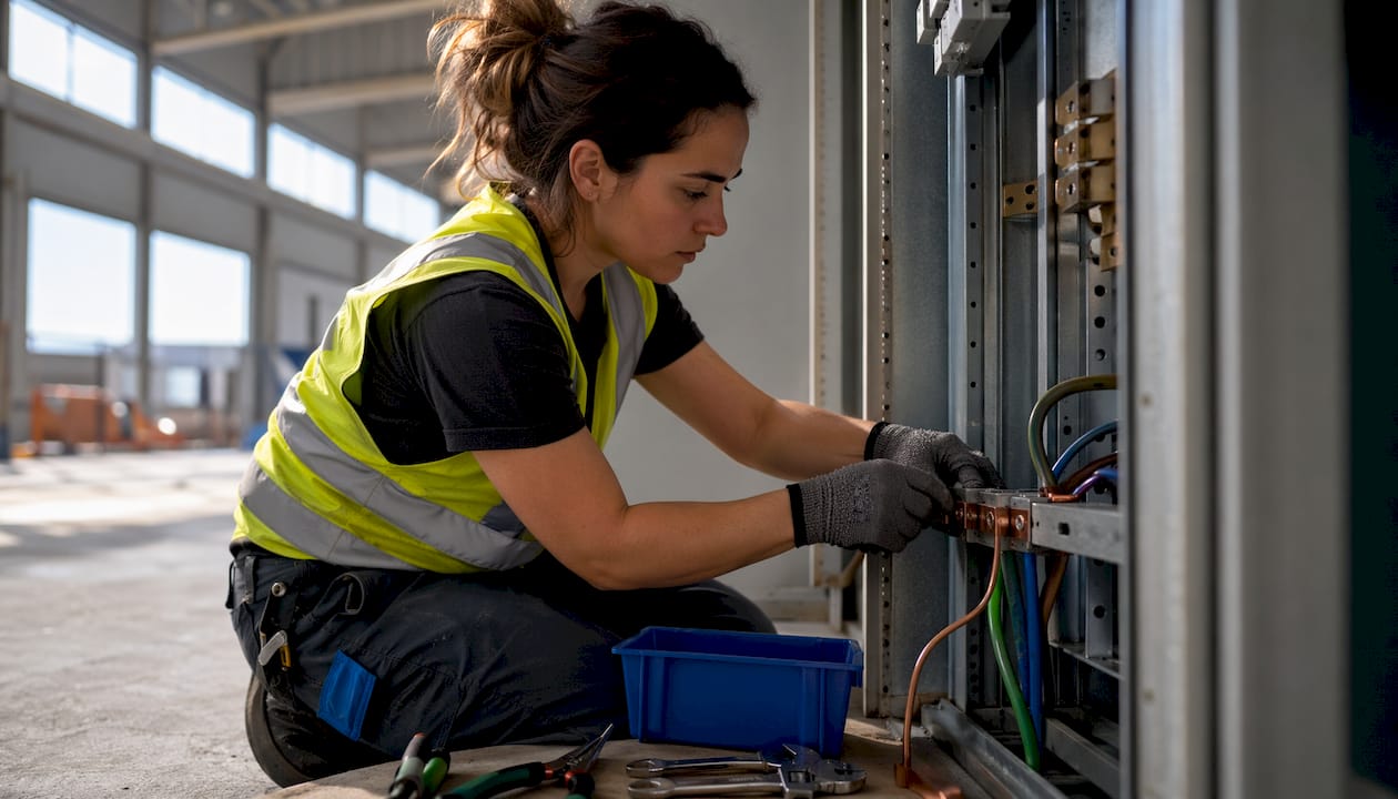
Pro Tip: On commercial projects with multiple disconnects, verify that each disconnect enclosure has its own bonding jumper sized per NEC 250.28. A single jumper at the meter base does not satisfy the requirement for separately enclosed disconnects.
What are common grounding electrodes and how are they installed?
The grounding electrode system is the physical connection between the electrical installation and the earth. NEC 250.52 recognizes several electrode types, each with specific installation and performance criteria.
Accepted electrode types and installation criteria
- Concrete-encased electrode (Ufer): At least 20 feet of bare copper conductor, 4 AWG or larger, or rebar encased in concrete footing in contact with earth. This is the preferred electrode for new construction.
- Ground rods: Minimum 8 feet long, driven vertically or at an angle not exceeding 45 degrees. A single rod must achieve 25 ohms or less; if it does not, a second rod must be installed at least 6 feet away and bonded to the first.
- Metal underground water pipe: Must be in contact with earth for at least 10 feet. NEC requires supplementation because plastic piping increasingly replaces metal in new construction, eliminating this electrode.
- Ground ring: Bare copper conductor, 2 AWG or larger, encircling the building at least 2.5 feet below grade.
- Plate electrodes: At least 2 square feet of bare metal surface in contact with earth, buried at least 30 inches below grade.
Connection requirements and listed hardware
NEC 250.70 requires that connections to grounding electrodes use listed connectors. Connections buried in earth or encased in concrete must use irreversible compression connectors or exothermic welding. Standard mechanical set-screw clamps are not permitted for buried applications because corrosion increases impedance over time, degrading the electrode’s effectiveness.
Modern construction in Alberta increasingly uses PEX and CPVC plumbing, which eliminates the metal water pipe as a qualifying electrode. Engineers and contractors must specify alternative electrodes, typically a concrete-encased electrode or ground ring, during the design phase rather than discovering the deficiency at rough-in inspection.
How to size grounding and bonding conductors correctly
Correct conductor sizing is the most frequently failed element during electrical inspections. The two governing tables address different conductors with different sizing bases, and applying the wrong table produces a non-compliant installation.
-
Identify the overcurrent device rating for EGC sizing. Pull NEC Table 250.122. A 15A breaker requires a minimum 14 AWG copper EGC. A 20A breaker requires 12 AWG. A 100A breaker requires 8 AWG copper. The EGC must run with the circuit conductors it protects.
-
Identify the largest service entrance conductor for GEC sizing. Pull NEC Table 250.66. A service using 2/0 AWG copper conductors requires a 4 AWG copper GEC. A service using 350 kcmil conductors requires a 2 AWG GEC. The GEC connects the neutral bus to the grounding electrode system.
-
Verify that EGC size increases with conductor upsizing. When circuit conductors are increased in size to compensate for voltage drop, the EGC must be proportionally increased per NEC 250.122(B). This rule catches many retrofit installations where conductors were upsized without adjusting the ground wire.
-
Check bonding jumper sizing separately. Main bonding jumpers and system bonding jumpers are sized per NEC 250.28 using Table 250.66, based on the service conductor size, not the breaker rating.
-
Document sizing decisions for inspection. On commercial projects, electrical inspections proceed faster when the engineer of record provides a sizing schedule showing the table reference, input value, and resulting conductor size for each grounding and bonding conductor.
Pro Tip: On retrofit projects, always measure the existing service conductor size before specifying replacement grounding conductors. Panels are frequently upgraded without replacing the GEC, leaving an undersized conductor that fails Table 250.66 verification.
What are the bonding requirements for metal piping and building steel?
Bonding requirements extend beyond the service equipment to all conductive systems within the building. Unbonded metal creates shock hazards and prevents fault clearing on circuits that contact those surfaces.
- Interior metal water piping (NEC 250.104(A)): Must be bonded to the service equipment, panelboard, or grounding electrode system. The bonding conductor is sized per Table 250.102(D) based on the service or feeder size supplying the building.
- Metal gas piping (NEC 250.104(B)): Must be bonded to the electrical system. The bonding conductor is sized per Table 250.102(D). Gas piping that contacts energized conductors without a bond creates an electrocution hazard at every appliance connection.
- Structural steel and metal building frames: Must be bonded where they are likely to become energized. NEC 250.104© addresses metal frames of buildings, requiring bonding to the grounding electrode system.
- CSST gas piping: Corrugated stainless steel tubing requires special bonding for lightning protection because lightning-induced surges can puncture the thin wall of CSST, causing gas leaks and fires. Bonding CSST directly to the grounding electrode system at the point of entry is the accepted method.
- Listed connectors and approved methods: All bonding connections must use listed hardware per NEC 250.92 and 250.104. Pipe clamps must be listed for the application. Connections to structural steel may use listed lugs, exothermic welds, or listed bonding clamps.
For specialized environments such as telecommunications rooms, dedicated low-impedance grounding bars bonded to the building system reduce noise and surge exposure on sensitive equipment. This goes beyond the minimum NEC requirement but is standard practice in data center and telecom design.
Key Takeaways
Proper grounding and bonding requires applying the correct NEC table, electrode type, and bonding method for each component; no single element substitutes for another.
| Point | Details |
|---|---|
| Bonding clears faults; grounding stabilizes voltage | Never rely on the grounding electrode to trip breakers. Only a bonded, low-impedance path does that. |
| Use the correct sizing table | EGC sizing uses Table 250.122 by breaker rating; GEC sizing uses Table 250.66 by service conductor size. |
| Bond all electrodes together | NEC 250.50 requires every electrode present at the structure to be connected into one grounding electrode system. |
| CSST requires direct bonding | Lightning surges can puncture CSST; bond it directly to the grounding electrode system at the point of entry. |
| Retrofit projects need conductor verification | Upsized circuit conductors require proportionally upsized EGCs per NEC 250.122(B). |
Why most grounding defects come down to one misunderstanding
After reviewing electrical designs across dozens of commercial and residential projects, the single most persistent error is treating grounding and bonding as synonyms. Electricians install a ground rod, connect it to the neutral bar, and consider the system complete. That installation stabilizes voltage. It does not clear faults.
Many electricians conflate these functions, and the consequences show up at inspection or, worse, during a fault event. I have seen panels where every circuit had a green wire landed on the neutral bar, but the equipment grounding conductors were never run back through the conduit. The system looked grounded. Under fault conditions, it was not bonded.
The second most common error involves the sizing tables. Engineers and contractors who learned on older code cycles sometimes apply Table 250.66 to EGC sizing or vice versa. The 2026 NEC clarifications on this point are worth reading carefully, particularly for services above 200A where the two tables diverge significantly.
My practical advice: treat bonding verification as a separate checklist item from grounding verification. Confirm the grounding electrode system is complete and all electrodes are bonded together. Then, independently confirm that every metal enclosure, raceway, and equipment frame has a continuous, listed, low-impedance path back to the service. These are two separate inspections, not one.
For retrofit work in older Alberta buildings, the plastic plumbing issue deserves specific attention. A building that relied on a metal water pipe electrode for decades may now have no qualifying electrode at all after a plumbing renovation. Specifying a concrete-encased electrode or ground ring at the design stage prevents a costly post-construction fix.
— Sanjay
Futuregenconsulting: NEC-compliant electrical design for Alberta projects
Electricians and engineers working on complex grounding and bonding systems benefit from engineering support that goes beyond field interpretation of code tables.

Futuregenconsulting delivers MEP engineering services for residential and commercial projects, with over 30 years of experience in electrical system design, power distribution, and code compliance. The firm’s electrical engineers produce grounding and bonding designs that specify electrode types, conductor sizes, bonding jumper schedules, and listed connector requirements, all referenced to the current NEC edition. For new construction and retrofit projects in Alberta, Futuregenconsulting provides the engineering documentation needed to pass inspection on the first review. Contact Futuregenconsulting to discuss your project’s grounding and bonding design requirements.
FAQ
What is the difference between grounding and bonding?
Grounding connects the electrical system to earth to stabilize voltage and dissipate surges. Bonding connects metal parts together to create a low-impedance fault path that operates overcurrent devices.
What NEC table governs equipment grounding conductor sizing?
NEC Table 250.122 governs EGC sizing based on the overcurrent device rating. A 20A breaker requires a minimum 12 AWG copper EGC; a 100A breaker requires 8 AWG copper.
When is a second ground rod required?
A second ground rod is required when a single rod does not achieve 25 ohms or less resistance to earth. The second rod must be installed at least 6 feet from the first and bonded to it per NEC 250.56.
Does GFCI protection substitute for equipment grounding in older buildings?
GFCI receptacles provide shock protection in ungrounded two-wire systems but do not establish equipment grounding. True equipment grounding requires running grounding conductors or bonding to a grounded circuit or grounding electrode system.
Why must CSST gas piping be bonded separately?
CSST has thin walls that lightning-induced surges can puncture, creating gas leak and fire hazards. Direct bonding of CSST to the grounding electrode system at the building entry point is the accepted method per NEC 250.104(B).