
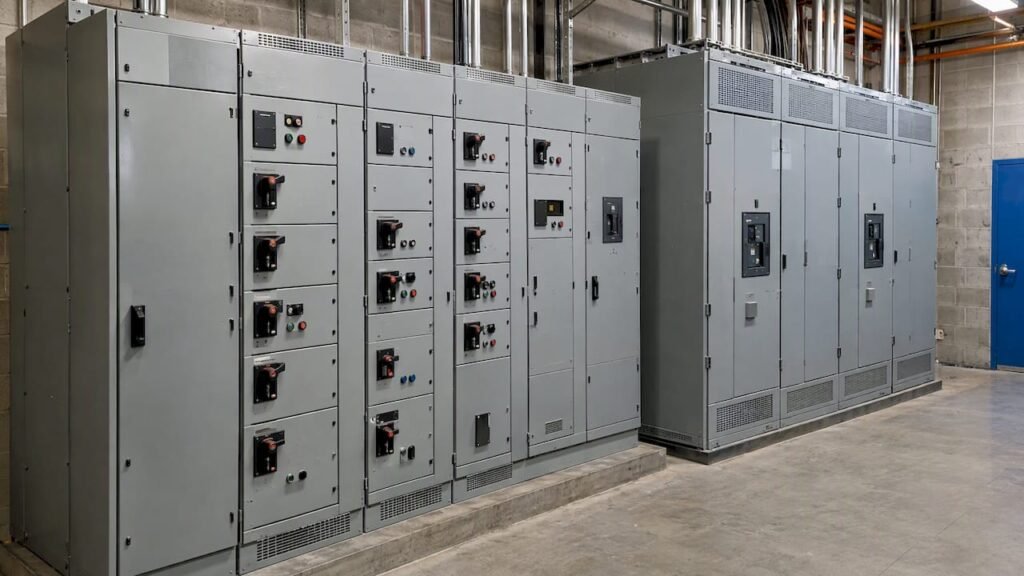
Switchgear and a motor control centre (MCC) are both metal-enclosed electrical assemblies, and both appear on the one-line diagram of most industrial and large commercial buildings, yet they serve different functions. Switchgear controls, protects and isolates the distribution of power. An MCC groups motor starters, controllers and disconnecting means in a common enclosure so that motors can be started, stopped and protected from one location. In a typical facility, power passes through switchgear first and then reaches the loads, including the MCC, which in turn serves the motors.
This article explains the distinction in the terms used by Ontario regulators and Canadian standards, shows where each assembly sits in a distribution system, and identifies the specification decisions that affect permitting, procurement and long-term safety.
TL;DR
- Switchgear manages where power goes and isolates faults; an MCC manages what the power does at the motor level.
- The Electrical Safety Authority (ESA) defines an MCC as an assembly of individual motor starters in a common enclosure, each with its controller and disconnecting means, and treats it separately from switchgear for inspection purposes.
- Switchgear spans low, medium and high voltage, whereas MCCs are low-voltage assemblies, generally 750 V or less.
- Switchgear lead times of up to three years are now reported for high-voltage equipment, so the selection should be settled during early design, not after tender.
- A manual motor controller is not a motor disconnect unless it is marked “Suitable as Motor Disconnect”; confirm this on every drawing and in the field.
Table of Contents
- What switchgear does
- What a motor control centre does
- MCC vs. switchgear at a glance
- How the two work together in a building
- Voltage classes and what they mean for selection
- Code and standards framework in Ontario
- The motor disconnect pitfall
- Procurement, lead times and cost risk
- Our perspective
- Specifying the right assembly: a practical checklist
- How FutureGen Consulting supports these decisions
- FAQ
- Sources
What switchgear does
Switchgear is a general term for the assemblies of breakers, switches, fuses, buses and protective relays that control, protect and isolate electrical equipment. Its purpose is the safe handling of bulk power: connecting a source to a distribution system, sectionalizing that system, and clearing faults so that a problem in one branch does not take down the entire facility. Industry research published by Electro Federation Canada describes switchgear as critical grid infrastructure for controlling and protecting medium- and high-voltage electrical flows, with fault isolation and equipment protection as its core functions.
In building projects, switchgear typically appears at the following points:
- The main service entrance, where utility power is received and metered or transformed.
- Secondary distribution, where a main breaker feeds a number of feeder breakers serving panelboards, transformers and large loads.
- Generator and standby paralleling arrangements, where several sources must be coordinated and interlocked.
- Medium-voltage distribution within campuses, hospitals, data centres and industrial plants.
Because switchgear sits at the top of the distribution hierarchy, its ratings are driven by available fault current, continuous current, voltage class and the need for selective coordination with upstream and downstream devices. These inputs come from system studies and not from a catalogue. For the broader question of how switchgear differs from switchboards, including the effect of the 1,000 V threshold, see our companion article on switchboard vs. switchgear in Canada.
What a motor control centre does
An MCC is a purpose-built assembly for motor loads. The ESA, in its 2026 fee guide, treats a motor control centre as a specific type of assembly containing multiple individual motor starters, and the same guide categorizes switchgear separately. Each section, often called a bucket, cubicle or unit, typically holds a disconnecting means, short-circuit protection, a contactor or starter, overload protection and control wiring. The buckets share a common vertical and horizontal bus arrangement within a single lineup.

The practical benefit is consolidation. Instead of mounting separate starters throughout a mechanical room or process area, the designer places them in one location, with consistent wiring, labelling and maintenance access. Modern MCCs may also include variable frequency drives, soft starters, programmable controllers, metering and communications that connect motor data to a building automation or plant control system.
The EFC research cited above describes MCCs as specialized assemblies for low-voltage motor control, in the range of 750 V or less, within industrial and commercial facilities. Typical applications include pumps, fans, compressors, conveyors, chillers, boiler plant, and the HVAC and fire pump auxiliaries that make up much of a building’s mechanical load.
MCC vs. switchgear at a glance
| Criterion | Switchgear | Motor control centre (MCC) |
|---|---|---|
| Primary function | Control, protect and isolate power distribution | Start, stop, control and protect multiple motors |
| Position in the system | Upstream: service entrance, main and feeder distribution | Downstream: fed from distribution, serves motor loads |
| Typical voltage range | Low, medium and high voltage | Low voltage, generally 750 V or less |
| Main protective devices | Power circuit breakers, fuses, protective relays | Motor circuit protectors or fuses, contactors, overload relays |
| Typical units | Breaker compartments | Starter buckets, with or without drives |
| Driving design inputs | Fault current, coordination, source arrangement | Motor horsepower, starting method, control scheme |
| ESA fee treatment | Per metal-enclosed switchgear assembly | Per connected cubicle |
The table shows why the two are not interchangeable. Switchgear is organized around the circuit and its protection, while an MCC is organized around the motor and its control. A facility with a large motor population usually needs both, and the engineering question is how they are arranged and coordinated.
How the two work together in a building
A representative distribution path in an industrial or large commercial building runs as follows. Utility power arrives at a service entrance, passes through main switchgear, and is distributed to feeders. One feeder serves lighting and general-purpose panelboards through step-down transformers. Another feeder serves the mechanical plant and terminates at an MCC. Within the MCC, each bucket serves one motor or a small group of motors, such as a chilled water pump, a supply fan or a cooling tower fan.
This arrangement has several consequences for design:
- Protection must be coordinated across both assemblies. The feeder breaker in the switchgear, the MCC main device, and the branch protection in each bucket have to trip in the correct order so that a motor fault does not de-energize the entire plant.
- Short-circuit ratings must be consistent. The MCC bus bracing and the interrupting ratings of its bucket devices must be equal to or greater than the available fault current at its location, which depends on the upstream transformer and switchgear. A power system study establishes these values before equipment is specified.
- Emergency and standby power must be planned. If an MCC serves life-safety or critical process loads, the transfer arrangement, generator sizing and motor starting behaviour on standby power influence both the switchgear and the MCC. Our overview of transfer switch types covers the options.
- Physical space and access must be reserved. Both assemblies need working clearances, ventilation, cable entry and a route for delivery and replacement. These are routinely underestimated on renovation projects.
For a fuller picture of how these assemblies fit into a building’s electrical system, see our guide to power distribution design for Ontario buildings.
Voltage classes and what they mean for selection
Voltage is the clearest practical divider. Switchgear is manufactured across low-voltage, medium-voltage and high-voltage classes, and the EFC research describes the high-voltage category as part of the grid infrastructure that is under supply pressure. MCCs, by contrast, remain in the low-voltage class. A motor that is too large or too remote for low-voltage starting may be served by a medium-voltage starter lineup, which is a related but distinct product and should not be assumed to be a standard MCC.
The selection logic is usually as follows:
- Low-voltage motors in groups: an MCC fed from low-voltage distribution is the conventional solution.
- A single large motor or a few motors: a starter in the switchgear lineup, a standalone starter or a drive may be more economical than an MCC.
- Very large motors: medium-voltage starting equipment, supplied from medium-voltage switchgear, is evaluated on the basis of motor size, cable length and voltage drop.
- Primary distribution: switchgear, with its breaker-based protection and relay coordination, is the appropriate assembly regardless of motor count.
Code and standards framework in Ontario
In Ontario, electrical installations are governed by the Canadian Electrical Code, Part I (CSA C22.1), as modified by the Ontario amendments published by the ESA. The ESA is the administrative authority responsible for inspection and enforcement. ESA bulletin 36-15-* addresses the approval of high-voltage equipment and notes that such equipment is to be approved where certification product standards accredited by the Standards Council of Canada are available. Our research identifies CAN/CSA C22.2 No. 31 as the applicable product standard for switchgear assemblies, and the same ESA framework requires that installations be carried out by licensed electrical contractors and verified against code requirements before connection.
Several practical points follow:
- Equipment must carry recognized certification marks. Specifications should state the required certification for each assembly, and shop drawings should be reviewed against it before release for manufacture.
- Field-assembled or modified equipment draws scrutiny. Where an assembly is altered after certification, the inspection route may change, so any deviation should be confirmed with the ESA before construction.
- Inspection fees follow the assembly type. According to the ESA’s 2026 fee guide, the fee as of July 2026 is $143 for each metal-enclosed switchgear and $57 for each connected cubicle, which is the basis on which MCC and switchgear lineups are priced differently for inspection. Fees are updated periodically, so budgets should be checked against the current guide.
- Documentation differs. Because the ESA distinguishes MCCs from general distribution assemblies, the permit submission should identify each assembly by its correct type. Our guide to ESA plan review in Ontario outlines when a design must be submitted and what reviewers look for.
Alberta projects follow the Canadian Electrical Code as adopted and administered under that province’s own regime, so the Ontario amendments and ESA procedures described here should not be assumed to apply there.
The motor disconnect pitfall
One of the most consequential errors in motor circuit design involves the disconnecting means. A manual motor controller (MMC) can look nearly identical to a disconnect switch, but ESA safety communications are explicit that appearance is not a basis for identification. In ESA Flash Notice 19-33-FL, the authority describes a worker who was electrocuted during maintenance on a pump motor, with an MMC involved in the fatality. The notice states that only devices marked “Suitable as Motor Disconnect” may serve as the disconnecting means, in accordance with Ontario Electrical Safety Code Rule 28-602(3).
This is relevant to the MCC discussion because each bucket must provide a compliant disconnecting means, and because field modifications and retrofits frequently introduce non-compliant devices. In practice, the design team should:
- Specify the disconnecting means for each motor circuit explicitly, with the required marking.
- Require that shop drawings and bucket schedules identify the device type and its marking.
- Include a verification step in the construction review, so that the installed device matches the approved design.
- Ensure that lockout procedures for maintenance personnel refer to the actual disconnecting device.
The same discipline applies to switchgear, where the isolating means, grounding provisions and interlocks must be verified before any maintenance is planned.
Procurement, lead times and cost risk
Selection is no longer only a technical question. The EFC research reports lead times of up to three years for high-voltage breakers and switchgear and notes that relying on historical timelines is a major scheduling risk. It also points to potential cost fluctuations in the range of 20 to 25 percent, driven by global supply chain volatility and material price trends. These figures apply most directly to high-voltage equipment, and low-voltage assemblies, including MCCs, may follow different timelines, so manufacturer quotations should be requested for each assembly and not inferred from this range.
The consequences for project delivery are straightforward:
- Define the electrical single-line diagram and load list early. Equipment orders cannot be placed until ratings, voltage, bus configuration and protective devices are fixed.
- Issue long-lead equipment packages ahead of the full construction tender, where the owner’s procurement rules permit.
- Carry an escalation allowance in the budget, and update it when quotations are received. A detailed electrical construction cost estimate prepared at the design stage gives the owner a defensible baseline.
- Consider phasing and spare capacity. Specifying space for future buckets or feeder breakers can avoid a second long procurement cycle when the facility expands.
The EFC research also observes that the technology for both switchgear and MCCs is mature, while the energy transition is driving a shift toward digital monitoring and SF6-free gas insulation. SF6-free designs reduce environmental impact but, according to the same research, currently face questions about winter resilience in the Canadian climate. For outdoor or unheated installations in Ontario, this is a point to discuss with manufacturers during selection.
Our perspective
In our experience on Ontario residential and commercial projects, the MCC vs. switchgear question is rarely a choice between two products. It is a question of how responsibilities are divided within the distribution system, and the best outcomes come from settling that division before equipment is chosen. We start from the load list and the single-line diagram, establish the fault levels, and only then decide which functions belong in switchgear, which in an MCC, and which in standalone starters or drives.

Three habits recur on projects that proceed without permit delays. First, the design identifies each assembly by its regulatory category, so that the ESA submission and the equipment schedule use the same language. Second, protective device coordination is documented and not assumed, which is why we treat system studies as a design input and not as a late deliverable. Third, the construction review includes a check of the disconnecting means in each motor circuit, because the consequences of an incorrect device are severe and the error is easy to miss.
The Chair of the EFC Technical Advisory Council, Vladimir Gagachev, has emphasized that adherence to the Canadian Electrical Code and manufacturer certifications, together with early consultation, is what protects a project from regulatory delay, and not hardware selection alone. That is consistent with how we approach each assignment.
— Sanjay
Specifying the right assembly: a practical checklist
Before issuing a specification or requesting quotations, the project team should be able to answer the following:
- What is the available fault current at the point of installation, and has it been confirmed by a short-circuit study?
- What is the nominal system voltage, and does any equipment fall above the low-voltage threshold?
- How many motors will be served, what are their ratings, and which will require variable speed control or soft starting?
- Which loads are life-safety or critical, and how will they be supplied during a utility outage?
- What are the physical constraints: room size, working clearances, delivery route, ventilation, and exposure to temperature extremes?
- Which certification marks are required, and who will verify them at shop drawing review and at site inspection?
- What are the quoted lead times, and how do they compare with the construction schedule?
- Is future expansion anticipated, and has spare capacity been provided in both assemblies?
A team that can answer these questions has usually resolved the MCC and switchgear decision, and the documents that follow tend to move through ESA review with fewer comments.
How FutureGen Consulting supports these decisions
FutureGen Consulting Inc. provides mechanical and electrical engineering design for residential and commercial projects in Ontario, including power distribution design, power system studies, emergency power design, construction review, and electrical construction cost estimation, with permit-ready, engineer-stamped drawings. Owners, contractors, architects and property managers who are deciding how to arrange switchgear, MCCs and standby power can review our power distribution and related services or contact us through the FutureGen Consulting website to discuss a project.
FAQ
Is an MCC the same as switchgear?
No. Switchgear controls, protects and isolates power distribution, using breakers, buses and protective relays, and is manufactured in low, medium and high voltage classes. An MCC is a low-voltage assembly of motor starters, each with its controller and disconnecting means, in a common enclosure. The ESA treats them as separate assembly types for inspection purposes.
Can an MCC be fed from switchgear?
Yes, and this is the common arrangement. A feeder breaker in the distribution switchgear supplies the MCC bus, and the MCC then serves individual motors through its buckets. The protective devices in both assemblies must be coordinated, and the MCC bus bracing must withstand the available fault current at its location.
What is the difference between a VFD and an MCC?
A variable frequency drive (VFD) is a single device that controls the speed of one motor by varying frequency and voltage. An MCC is an assembly that houses many starters and may include VFDs as individual units. A VFD is therefore a component that can be installed inside an MCC or mounted separately.
Does an MCC require ESA inspection in Ontario?
Electrical installations in Ontario must be performed by licensed electrical contractors and verified to meet code requirements before connection, with inspection by the ESA. The ESA fee guide prices MCCs by connected cubicle and switchgear by assembly, so each should be identified accurately in the submission. The current fee guide should be consulted, as fees change.
Can a manual motor controller serve as the motor disconnect?
Only if it is marked “Suitable as Motor Disconnect”. The ESA warns that these devices can look identical to disconnect switches and that mistaking one for the other has contributed to a fatality. Verify the marking on the device itself, not its appearance.
Sources
- ESA 2026 Wiring Fee Guide
- Electro Federation Canada: Building Canada’s Future Electricity Grid
- ESA Bulletin 36-15-*: High voltage equipment standards
- ESA Flash Notice 19-33-FL: Manual motor controllers used as a disconnecting means
- Ontario Amendments to the Canadian Electrical Code, Part I, C22.1
- 2024 EFC Award of Excellence Winner: Vladimir Gagachev, Eaton