

A single line diagram is defined as a simplified schematic representation of a three-phase power system that depicts multiple conductors as a single line. Known in industry as an SLD or one line diagram electrical drawing, it serves as the master reference for all major downstream activities, including arc flash studies, short-circuit analysis, and protection coordination. Every electrical engineer and student working on residential or commercial projects in Alberta must understand what an SLD contains, how to read it, and why keeping it current is a professional obligation, not an optional task.
What does a single line diagram need to include?
A complete SLD captures every element of a power system in logical sequence from source to load. Standard industry conventions require SLDs to include sources, transformer specifications, switching device ratings, busbar ratings, cable details, and protection schemes with ANSI codes, organized in power flow sequence that matches the real switchgear layout.
The following elements are mandatory for a professionally valid SLD:
- Utility and generator sources: Rated capacity, fault contribution levels, and point of common coupling data.
- Transformer specifications: kVA rating, primary and secondary voltage, percentage impedance, and vector group (for example, Dyn11).
- Switching devices: Circuit breaker and fuse ratings, interrupting capacity, and ANSI protection function codes such as 50/51 for overcurrent and 87 for differential protection.
- Busbar ratings: Continuous current rating, short-circuit withstand rating, and unique bus identification labels.
- Cable details: Conductor size, insulation type, length, and routing reference to cable schedules.
- Load information: Connected kW or kVA, demand factor, and load type (motor, lighting, HVAC).
- Earthing arrangement: System grounding method, such as solid, resistance, or impedance grounding.
- Metering and protection schemes: Current transformer ratios, relay types, and tie breaker statuses.
The diagram layout follows either a left-to-right or top-to-bottom convention, matching the physical sequence of switchgear from the incoming supply to the final distribution boards. This consistency allows any engineer reviewing the drawing to trace power flow without ambiguity.
Pro Tip: Always cross-reference the SLD against the electrical load list before finalizing. A load list that does not match the SLD is a sign that one document has been updated without the other, which creates downstream errors in fault and arc flash calculations.

SLD symbols follow IEC 60617 standards globally. North America uses ANSI symbols, which represent equipment such as circuit breakers, transformers, generators, and protection devices in a standardized visual language. Engineers working across Canadian provinces, including Alberta, must confirm which symbol set applies to their project before issuing drawings for review.
How does a single line diagram differ from three-line and wiring diagrams?
The three diagram types serve different purposes, and confusing them causes real errors on projects. An SLD represents one phase to capture system behavior in balanced three-phase systems, simplifying analysis while covering the full power topology. Three-line diagrams show each phase individually and are used only when phase unbalance or phase-specific protection analysis is required.
| Diagram type | Primary use | Level of detail |
|---|---|---|
| Single line diagram | System overview, fault studies, arc flash, load flow | Equipment ratings, protection schemes, power flow |
| Three-line diagram | Phase-specific protection, unbalanced system analysis | Individual phase conductors, CT/PT connections |
| Wiring schematic | Installation, termination, and troubleshooting | Terminal numbers, conductor colors, physical routing |
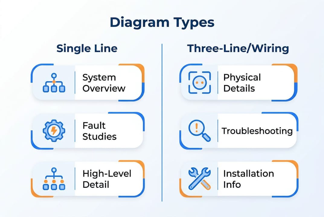
An SLD is not suitable for physical installation troubleshooting. Detailed schematics and wiring diagrams are necessary for that work because SLDs lack physical wiring and terminal detail. Using an SLD to trace a fault to a specific terminal block will produce incorrect results and waste time on site.
A complete drawing set for any commercial or multi-unit residential project in Alberta includes all three diagram types. Each serves a distinct stage of the project lifecycle: the SLD drives design and analysis, the three-line diagram supports protection relay commissioning, and the wiring schematic supports installation and maintenance. Omitting any one of them creates gaps that affect both compliance and safety. Engineers responsible for electrical safety in multi-unit buildings should confirm that all three diagram types are specified in the project scope from the outset.
How do you read and interpret a one line schematic for engineering analysis?
Reading an SLD effectively requires a structured approach. Tracing power flow, calculating load currents, checking breaker ratings against fault currents, and reviewing protection coordination curves are the four core tasks every engineer performs when using an SLD for analysis.
The following sequence applies to most load flow and fault analysis tasks:
- Identify all sources. Locate the utility supply point and any on-site generation. Note the available fault current at the point of common coupling, typically expressed in kA symmetrical.
- Trace the power flow path. Follow the single line from the main switchboard through each distribution board to the final loads. Confirm that every branch is labeled and that no paths are missing.
- Calculate load currents. Sum the connected loads at each feeder level. Apply demand factors where specified and confirm that cable and busbar ratings are not exceeded.
- Evaluate breaker interrupting ratings. Compare the available fault current at each bus against the interrupting capacity of the protective devices. A breaker rated below the available fault current is a code violation and a safety hazard.
- Review protection coordination curves. Confirm that upstream devices operate slower than downstream devices under fault conditions. This selectivity prevents unnecessary outages and protects equipment.
- Extract data for arc flash calculations. Protection settings and fault levels annotated on the SLD are critical inputs for arc flash calculations and safe equipment operation. Missing relay settings or fault data at this stage invalidates the entire arc flash study.
Common pitfalls include missing transformer impedance values, unlabeled tie breakers, and protection settings that have been changed in the field but not updated on the drawing. Each of these gaps produces unreliable analysis results. Understanding arc fault and ground fault protection principles helps engineers identify which protection settings on the SLD are most critical to verify before starting any study.
Pro Tip: Before starting any engineering analysis, verify SLD completeness against a checklist that includes fault levels, transformer impedances, ANSI protection codes, and cable ratings. An incomplete drawing produces an incomplete study, and an incomplete study creates professional liability.
Best practices for maintaining and updating single line diagrams
Outdated or incomplete SLDs make safety calculations like arc flash studies unreliable and increase operational risks. This is not a theoretical concern. A transformer replacement, a new feeder addition, or a relay setting change that goes unrecorded on the SLD can cause the next arc flash study to underestimate incident energy by a significant margin.
The following practices keep an SLD current and professionally valid throughout a project’s lifecycle:
- Establish a formal change management process. Every modification to the electrical system, whether a new circuit, a replaced breaker, or a changed relay setting, must trigger a mandatory SLD update before the work is closed out.
- Assign clear documentation responsibility. One named engineer or technician must own the SLD at each project phase. Shared responsibility without clear ownership produces gaps.
- Conduct field verification before updates. Never update an SLD from memory or verbal reports. Verify nameplate data, relay settings, and cable sizes physically before revising the drawing.
- Apply revision control. Every SLD revision must carry a revision number, date, and description of changes. This creates an audit trail that supports regulatory compliance and professional accountability.
- Schedule periodic reviews. Align SLD reviews with planned maintenance shutdowns or system modifications. A review cycle tied to physical work ensures the drawing reflects actual site conditions.
- Refuse to sign off on incomplete drawings. Experts recommend specifying SLD completeness explicitly in consultant terms and refusing signoff on incomplete diagrams. This protects both the engineer and the client.
The consequences of ignoring SLD updates extend beyond compliance. An incorrect arc flash label based on an outdated SLD exposes workers to incident energy levels higher than their personal protective equipment is rated for. That outcome is preventable with disciplined documentation practices.
Key Takeaways
A single line diagram is the master electrical document that drives every safety study, design decision, and compliance review on a project. Its accuracy is not optional.
| Point | Details |
|---|---|
| SLD is the master reference | All arc flash, fault, and coordination studies depend on a complete and current SLD. |
| Mandatory content is defined by standard | ANSI codes, transformer impedance, fault levels, and cable data must all appear on a valid SLD. |
| SLD differs from wiring diagrams | Use three-line diagrams and wiring schematics for phase-specific analysis and installation work. |
| Reading requires a structured sequence | Trace power flow, verify breaker ratings, and extract protection settings before starting any study. |
| Maintenance requires formal process | Assign ownership, apply revision control, and update the SLD after every system modification. |
Why the SLD is the document I will not let a project proceed without
Every project I have reviewed that produced unreliable safety studies had one thing in common: an SLD that was either incomplete or had not been updated since the original design. The drawing looked finished. It had a title block, a revision number, and a stamp. But the relay settings were from the commissioning phase three years earlier, and two feeders added during a tenant fit-out were missing entirely.
The SLD is not just a drawing. It is the master record that every other safety and design decision references. When it is wrong, everything downstream is wrong. Arc flash labels are wrong. Breaker coordination is wrong. Load calculations are wrong. The errors do not announce themselves. They sit quietly until someone gets hurt or a fault cascades further than it should.
My advice to every engineer working on commercial or residential projects in Alberta is direct: specify SLD completeness requirements in your contract before the project starts. Define exactly what data must appear on the drawing, including fault levels, ANSI protection codes, transformer impedance, and cable details. Then refuse to approve the SLD until those requirements are met. That is not being difficult. That is practicing engineering responsibly.
The engineers who treat the SLD as a living document, updated after every system change, are the ones whose projects pass audits, whose arc flash studies hold up under scrutiny, and whose clients do not face costly rework. The Ontario Electrical Safety Code and equivalent Alberta standards both depend on accurate electrical documentation as the foundation for compliance. The SLD is where that foundation either holds or fails.
— Sanjay
Futuregenconsulting’s electrical design and SLD services
Accurate electrical documentation is the foundation of every safe and code-compliant building project. For engineers and developers working on residential and commercial projects across Alberta and Ontario, that foundation starts with a properly prepared power system diagram.

Futuregenconsulting delivers MEP engineering services with over 30 years of experience in electrical system design, including single line diagram preparation, protection coordination studies, and arc flash analysis. The firm’s electrical engineers produce SLDs that meet current ANSI and IEC standards, contain all mandatory data fields, and are structured for direct use in fault and load flow studies. Futuregenconsulting also supports ongoing documentation maintenance, ensuring that SLDs remain current through every phase of construction, commissioning, and facility operation. Contact Futuregenconsulting to discuss your project’s electrical design and documentation requirements.
FAQ
What is a single line diagram in electrical engineering?
A single line diagram is a simplified schematic that represents a three-phase power system using one line per circuit, showing equipment ratings, protection schemes, and power flow. It serves as the master reference for arc flash studies, short-circuit analysis, and protection coordination.
What symbols are used on a single line diagram?
North American SLDs use ANSI symbols to represent equipment such as circuit breakers, transformers, generators, and protection relays. Projects outside North America typically follow IEC 60617 standards for the same equipment types.
How does a single line diagram differ from a wiring diagram?
An SLD shows system topology, equipment ratings, and protection schemes at a high level, while a wiring diagram shows physical conductor routing, terminal numbers, and connection details. SLDs are used for system analysis; wiring diagrams are used for installation and troubleshooting.
What data must appear on a valid SLD for arc flash analysis?
A valid SLD for arc flash analysis must include available fault current at each bus, transformer impedance, protective device ratings, and ANSI relay function codes with settings. Missing any of these data points produces an invalid arc flash study.
How often should a single line diagram be updated?
An SLD must be updated after every modification to the electrical system, including new circuits, replaced equipment, or changed protection settings. Treating the SLD as a living document with formal revision control is the standard required for professional engineering practice.