

Fire alarm zoning divides a building into clearly identified areas so emergency responders can locate an activation quickly and operations teams can limit unnecessary disruption. Each zone corresponds to a discrete section of the building, reported separately at the Control and Indicating Equipment (CIE), giving the fire service a precise starting point rather than an entire floor or wing to search. Three standards govern this in Canada: CAN/ULC-S524:2019 for installation, CAN/ULC-S536 for inspection and testing, and the Ontario Fire Code (O. Reg. 213/07) for ongoing compliance obligations. NFPA 72 provides supplementary guidance widely referenced by Canadian designers.
Before reading further, confirm these three things:
- Check the CIE zone plan — verify it is mounted on or immediately adjacent to the panel, correctly oriented, and legible under emergency lighting.
- Verify zone labeling — confirm that panel zone labels match the as-built drawings and the physical zone plan.
- Schedule a zoning review — if the building has undergone any tenant fit-out, renovation, or occupancy change since the last commissioning, book a review with your fire alarm design team.
Key Takeaways
Effective fire alarm zoning requires code-grounded sizing, operationally logical boundaries, and a current zone plan mounted at the CIE, verified at commissioning and reviewed after every building change.
| Point | Details |
|---|---|
| Zone plan at the CIE | Mount a correctly oriented, legible zone plan on or adjacent to the panel; an absent or outdated plan is a major non-compliance. |
| Code area and storey limits | Non-sprinklered zones generally cannot exceed 2,000 m² or span more than one storey under OBC guidance. |
| Stakeholder engagement | Involve facility managers at the design stage to align zone boundaries with operational workflows and cause-and-effect requirements. |
| Post-renovation review | Any tenancy change, partition modification, or plant room relocation requires a full zone review before reoccupancy. |
| Futuregenconsulting | Provides engineer-stamped zone plans, commissioning support, and zoning audits for commercial buildings in Ontario. |
Standards and guidance to consult
- CAN/ULC-S524:2019 — Installation standard for fire alarm systems; governs device placement, panel requirements, zone configuration, and modern features including wireless devices and fault tolerance.
- Ontario Fire Code (O. Reg. 213/07) — Sets legal definitions, ongoing maintenance obligations, and cross-references to ULC standards for inspection, testing, and verification.
- CAN/ULC-S536 — Inspection and testing standard; specifies frequencies and procedures for routine inspection of fire alarm systems, including zone verification.
- CAN/ULC-S537 — Verification standard; governs the acceptance testing process at commissioning and after modifications.
- OBC Clause 3.2.4.9 — Sets zone area and storey limits referenced in Ontario building design; consult for sizing decisions on non-sprinklered and sprinklered floors.
- FIA Technical Bulletin: Zone Plans V2 — Detailed guidance on zone plan content, orientation, labeling, and the compliance consequences of an absent or inaccurate plan.
- NRC Canada: Voice Communication Systems (NBC Clause 3.2.4.22) — Covers selective zone messaging, two-way communication requirements, and intelligibility criteria for high-rise voice communication systems.
- BCAB-1731 — Appeal board decision on combined zone annunciation; useful precedent for understanding how zoning intent is interpreted in code disputes.
Table of Contents
- What fire alarm zoning means: detection, alarm, and annunciation zones
- How conventional and addressable systems handle zoning differently
- Zone sizing and layout: code limits and practical boundaries
- Annunciators, control panels, and the mandatory zone plan
- Evacuation staging, single-stage vs two-stage alarms, and voice communications
- Typical zone counts for common building types
- Design and audit best practices from practicing MEP engineers
- Verification, commissioning, and ongoing maintenance for zones
- Futuregenconsulting’s fire alarm zoning and design services
- Sources
What fire alarm zoning means: detection, alarm, and annunciation zones
Three distinct zone types appear in fire alarm design, and conflating them causes real problems during both design and emergency response.
Detection zones group the initiating devices (smoke detectors, heat detectors, manual pull stations) that share a common reporting circuit or address range. In a conventional system, every device wired to a single zone circuit reports as one zone. In an addressable system, each device carries a unique address, and the designer maps those addresses into logical detection zones at the panel. Either way, the detection zone is the smallest geographic unit the CIE can identify as the source of an activation.
Alarm and evacuation zones operate at a higher level. They define which notification appliances (horns, strobes, speakers) activate together in response to an alarm signal. An evacuation zone may span multiple detection zones, particularly in large open-plan buildings or multi-tenant facilities where a single detection event triggers notification across an entire floor or wing. The relationship between detection zones and evacuation zones drives the cause-and-effect programming at the panel, and getting that relationship wrong is one of the most common commissioning failures.
Annunciation zones refer to how the CIE and any remote annunciator panels display zone status. Zone numbering must be consistent across the physical panel, the electronic display, and the zone plan drawing. For emergency responders arriving at the front entrance, the annunciator panel and its zone plan are the first tools they use. Numbering that starts at the top floor and works downward, or that skips numbers arbitrarily, adds critical seconds to the search.
Pro Tip: Align detection zone boundaries with operational workflows, not just floor plates. Plant rooms, server rooms, and electrical switchgear rooms should each sit in their own dedicated zone. When a detector activates in a server room, the panel should say “Server Room Zone 4,” not “Ground Floor Zone 1” alongside 30 other devices. That specificity is what allows a targeted cause-and-effect response, such as shutting down HVAC to that room only, without triggering a building-wide evacuation.
A zone plan is not a technical diagram for the design file. It is the primary navigation tool the fire service uses under pressure, in smoke, with limited time. Every labeling decision made at the design stage either helps or hinders that search.
How conventional and addressable systems handle zoning differently
The panel type determines how zones are physically constructed and how granular the zoning can be, which directly affects commissioning complexity, fault tolerance, and the speed of emergency response.
Conventional systems
In a conventional system, zones equal circuits. Every device on a single two-wire circuit reports to the panel as one zone, with no individual device identification. A fault or activation on that circuit shows the zone number, nothing more. Zone granularity is therefore limited by the number of circuits the panel supports, and adding zones means adding circuits and wire runs. For small, straightforward buildings with predictable layouts, conventional systems remain cost-effective and straightforward to maintain.
Addressable systems
Addressable panels assign a unique address to each device. Zones are logical groupings defined in software, meaning a designer can create, modify, or split zones without rewiring. A single loop can carry hundreds of devices, each reported individually, and those devices can be grouped into any zone configuration the building requires. This flexibility is critical in multi-tenant office buildings, hospitals, and mixed-use developments where tenancy boundaries shift over time.
Addressable vs. conventional fire alarm systems differ most sharply in fault tolerance: a fault on one addressable device does not silence an entire zone, whereas a conventional circuit fault can take an entire zone offline. For large or complex sites, that distinction carries real operational weight.
| Factor | Conventional | Addressable |
|---|---|---|
| Zone definition | Physical circuit | Software-mapped address group |
| Device identification | Zone only | Individual device and zone |
| Fault impact | Entire zone circuit | Single device |
| Zone modification | Rewiring required | Software reconfiguration |
| Commissioning complexity | Lower | Higher (requires address verification) |
| Best suited for | Small, simple buildings | Large, complex, multi-tenant sites |
When a building has more than three or four floors, multiple tenancies, or critical infrastructure requiring selective cause-and-effect control, addressable zoning is the appropriate choice. The fire alarm system design guide for Ontario developers covers panel selection criteria in more detail.
Zone sizing and layout: code limits and practical boundaries
Zone size is not a designer’s preference. It is constrained by code, shaped by compartmentation, and tested against worst-case responder search distance.
The Ontario Building Code clause 3.2.4.9 limits detection zone coverage to no more than one storey and, for non-sprinklered floors, generally not more than 2,000 m² per zone. Sprinklered buildings may allow larger zones in some configurations, but the sprinkler system’s own zone boundaries should align with the fire alarm zones to avoid ambiguity about which area is involved. When sprinkler and alarm zones do not match, responders can receive conflicting information about the fire’s location.
Compartmentation drives zone boundaries more than floor area in many buildings. A fire-rated wall separating a parking garage from an office floor is a natural zone boundary, regardless of whether the combined area would technically fit within a single zone. Treating that wall as a zone boundary means an activation in the garage reports separately from an activation in the office, which is exactly the information the fire service needs to make a safe entry decision.
| Scenario | Zone boundary approach | Reason |
|---|---|---|
| Standard office floor, non-sprinklered, under 2,000 m² | One zone per floor | Meets code area limit; one-storey rule satisfied |
| Large floor plate over 2,000 m², non-sprinklered | Split into two or more zones | Code area limit exceeded |
| Sprinklered floor with fire-rated compartments | Zone boundaries follow compartment walls | Aligns alarm and suppression zones for responder clarity |
| Basement parking + ground-floor retail | Separate zones for each occupancy | Different occupancy risk; compartmentation boundary |
| Atrium spanning multiple floors | Dedicated atrium zone | Vertical spread risk; prevents false floor identification |
A Building Code Appeal Board decision (BCAB-1731) illustrates the consequence of ambiguous zoning: combining attic and fourth-storey balcony sprinklers in a single attic zone was challenged because it prevented correct identification of the zone of origin. The board’s reasoning reinforces that zoning must enable responders to identify where a fire started, not merely that something activated somewhere in a general area.
Voids, mezzanines, and large atriums require explicit treatment. A void space above a suspended ceiling that spans two fire compartments should not share a zone with the occupied floor below it. Mezzanines within a larger open space can share a zone with that space if they are within the same compartment and the combined area stays within code limits. Atriums that penetrate multiple floors typically warrant a dedicated zone, since an activation there carries a different risk profile than a standard floor activation.
A zone can be code-compliant by area and still fail operationally. If a 1,800 m² zone contains 40 devices spread across a maze of subdivided suites, a responder searching for the activated device faces a long, uncertain search. Targeting a practical worst-case search distance during design review, rather than simply checking the area figure, produces zones that actually work under emergency conditions.
Annunciators, control panels, and the mandatory zone plan
The zone plan is not optional documentation. FIA technical guidance states that a zone plan must be displayed on or immediately adjacent to the CIE, correctly oriented so that the plan’s north matches the building’s physical north as experienced from the panel’s location, and legible under emergency lighting conditions. Failing to provide an accurate, current plan is classified as a major non-compliance.
A compliant zone plan includes the following elements:
- Building orientation marker — north arrow or “you are here” indicator aligned to the panel’s physical position in the building.
- Zone numbering — every zone labeled with the same number shown on the panel display, with no gaps or duplications.
- Zone boundaries — clearly drawn boundaries showing which rooms, corridors, and spaces fall within each zone.
- Stair cores and exit routes — stairwells identified separately, since they are often in their own zone and are the primary responder access route.
- Service and plant rooms — labeled individually, particularly where they carry dedicated zones.
- Repeat annunciator locations — where remote annunciators exist, their locations marked on the plan.
- Legend — a key explaining symbols, zone numbering convention, and any abbreviations used.
- Revision date — the date the plan was last updated, so responders and inspectors can assess whether it reflects the current building layout.
An absent or outdated zone plan delays emergency response. If the panel shows “Zone 7 activated” but the zone plan on the wall shows a layout from before a major renovation, the fire service may search the wrong area entirely. That delay has consequences that extend well beyond a compliance citation. Practitioner guidance consistently identifies incorrectly oriented plans and ambiguous zone markings as the most common failures found during inspections.
Evacuation staging, single-stage vs two-stage alarms, and voice communications
How zones activate notification appliances depends on whether the building uses a single-stage or two-stage alarm strategy, and that choice cascades through every aspect of the cause-and-effect design.
Single-stage systems activate all notification appliances simultaneously when any initiating device triggers. Every occupant in the building receives the same evacuation signal at the same time. This approach suits smaller buildings, high-risk occupancies, and buildings where a full simultaneous evacuation is the appropriate response to any alarm.
Two-stage systems introduce an alert phase before a full evacuation signal. When a device activates, the system first sounds an alert tone (typically a slow whoop or intermittent signal) in the zone of origin and adjacent zones, while sounding a different signal or no signal in remote zones. Building staff investigate during the alert phase. If they confirm a fire, or if the alert phase timer expires without a staff response, the system escalates to a full evacuation signal. Two-stage operation is common in hospitals, hotels, and large office buildings where simultaneous full evacuation of all occupants carries its own risks.
Voice communication systems for high-rise buildings must support selective zone messaging and two-way communications, with intelligibility criteria referenced to IEC guidance. The system must be capable of transmitting voice messages to selected zones independently, and the intelligibility of those messages must be verified after furnishing and occupancy, since ambient noise and reverberation change significantly once a space is in use.
Intelligibility testing is frequently deferred until after occupancy, which means the commissioning record at handover may not reflect real-world performance. Designers should specify intelligibility verification as a post-occupancy requirement, not just a commissioning checkbox.
Occupancy type shapes the voice and zoning strategy significantly. A hospital uses defend-in-place protocols, so zone-by-zone selective messaging is critical. A shopping mall uses phased evacuation, with voice messages directing occupants in the affected zone first and adjacent zones next. A standard office building may use a simpler two-stage system with pre-recorded messages. Each scenario requires a different cause-and-effect matrix, and that matrix must be documented, tested, and reflected in the zone plan.
Typical zone counts for common building types
These examples are starting points for design conversations, not substitutes for a site-specific zoning analysis. Actual zone counts depend on floor area, compartmentation, occupancy risk, and the panel’s capacity.
| Building type | Typical zone breakdown | Notes |
|---|---|---|
| Small office (single storey, under 2000 m²) | 2–3 zones: main office, reception/lobby, plant room | Conventional panel often sufficient |
| Multi-storey office (5 floors, sprinklered) | 6 zones: one per floor plus stair cores and basement plant | Addressable preferred; stair zones support staged evacuation |
| Retail mall (single level, multiple tenants) | 8 zones: one per tenancy anchor, common areas, service corridors, plant | Zone boundaries follow tenancy demise lines |
| Warehouse (large open floor, non-sprinklered) | 3–5 zones: main floor split by area limit, loading dock, office/mezzanine, plant | Area limit drives splits; mezzanine separate if enclosed |
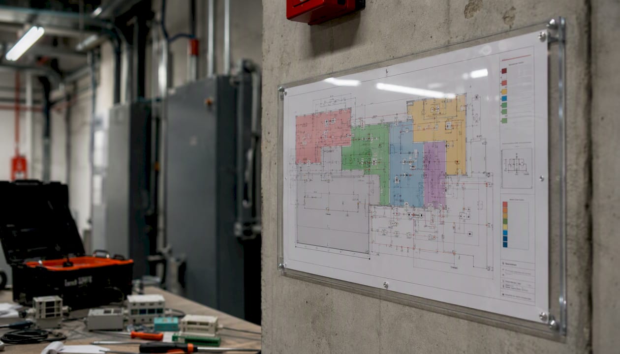
Pro Tip: Avoid zones that force responders to search multiple unrelated suites or rooms. A zone labeled “Ground Floor” that contains the lobby, two retail units, a storage room, and a plant room gives the fire service almost no useful information. Split by function and compartment, not by what was convenient to wire.
For a multi-storey office building, a practical zone scheme might look like this: Zone 1 for the basement plant and electrical rooms, Zone 2 for the ground-floor lobby and reception, Zones 3 through 7 for each occupied floor, Zone 8 for the stair cores (if they share a common pressurization system and can be treated as one zone), and Zone 9 for the rooftop mechanical penthouse. That nine-zone scheme gives responders a precise starting point for any activation and supports floor-by-floor staged evacuation without ambiguity.
The limitation of any sample scheme is that it cannot account for compartmentation details, tenant demise lines, or the specific cause-and-effect requirements of the building’s suppression and HVAC systems. Treat these examples as a framework for the design conversation, then adjust based on the actual building.
Design and audit best practices from practicing MEP engineers
Good zoning starts before the first device is placed. The design meeting checklist matters more than most facility managers realize.
At the design stage, the team should confirm operational zone boundaries with the facility manager before finalizing the zone map. Plant rooms, security control rooms, server rooms, and high-value storage areas each warrant their own zone, regardless of whether the floor area would permit combining them with adjacent spaces. The facility manager knows which areas require selective cause-and-effect responses, such as HVAC shutdown, door release, or suppression system activation, and that knowledge must feed directly into the zone design. Involving facility managers early prevents the most common design failure: zones that match wire-run efficiency but not operational or responder needs.
The most persistent construction-era failure is mismatched labeling. The physical panel labels, the electronic zone map on the display, and the as-built drawings frequently disagree with each other by the time a building reaches occupancy. Cross-checking all three during acceptance testing is the single most effective step to catch this before the building opens.
An audit schedule should follow this structure:
- Commissioning (pre-occupancy): Verify zone annunciation against as-built drawings, confirm zone plan orientation and labeling, test every device-to-zone mapping, and confirm cause-and-effect sequences.
- Handover verification: Confirm the zone plan is mounted at the CIE, the revision date is current, and the building operator has received training on panel operation.
- Annual inspection: Review zone plan currency against any layout changes, test a representative sample of devices per zone, and confirm HVAC and access control integrations are functioning.
- Post-renovation or occupancy-change review: Any partition change, tenancy modification, or plant room relocation triggers a full zone review. New walls can split a previously open zone into two distinct compartments, making the original zone boundary operationally misleading.
Functional zoning also supports business continuity. Well-defined zones allow a selective response to a contained incident, limiting unnecessary evacuation of unaffected areas. Grouping critical infrastructure into dedicated zones supports targeted cause-and-effect controls, such as activating suppression in a server room without triggering a building-wide evacuation. That operational precision is only possible when the zone design reflects how the building actually functions, not just how the wiring was run.
Verification, commissioning, and ongoing maintenance for zones
Commissioning is where design intent meets physical reality, and the gap between the two is often wider than expected.
At handover, the commissioning record should confirm:
- Every zone annunciates correctly at the CIE and at all remote annunciator panels.
- The zone plan mounted at the CIE matches the as-built zone layout, is correctly oriented, and carries the current revision date.
- Each device is mapped to the correct zone, verified by activating the device and confirming the panel response.
- Cause-and-effect sequences (HVAC shutdown, door release, suppression activation) trigger correctly for each zone.
- The two-stage timing sequence (where applicable) operates within the code-specified alert phase duration.
Ongoing testing and maintenance follow CAN/ULC-S536 for inspection and testing frequencies and CAN/ULC-S537 for verification. The Ontario Fire Code sets the legal obligation for ongoing maintenance and references these ULC standards directly. Routine inspections typically occur annually, with full verification at intervals specified by the authority having jurisdiction. After any modification to the fire alarm system, a partial or full re-verification is required before the building re-occupies the affected area.
Documents to maintain at the CIE and in the building’s maintenance file:
- Current as-built zone map (updated after every modification)
- Wiring diagrams for conventional systems; address lists for addressable systems
- Commissioning and verification test records
- Cause-and-effect matrix
- Maintenance log with dates, technician credentials, and findings
- Panel programming backup (for addressable systems)
Life safety compliance and maintenance guidance covers documentation requirements across jurisdictions. The zone plan itself should be inspected at every annual visit to confirm it remains current. Standards and guidance recommend that zone plans be legible under emergency lighting, which means checking that the panel area is adequately lit and that the plan’s print size and contrast remain readable after years of exposure.
An engineer’s perspective on what actually matters in zoning design
Most zoning failures are not code failures. The building passes inspection, the panel annunciates correctly, and the zone plan is mounted at the CIE. The failure is operational: zones that made sense on a drawing but confuse responders in an emergency, or zones that were never updated after a renovation because no one scheduled the review.
The conventional wisdom in fire alarm design is that compliance equals safety. It does not. A zone can satisfy every code requirement and still force a responder to search 40 rooms to find one activated detector. Code sets the floor, not the ceiling. The designers and facility managers who treat zoning as a living document, updated after every occupancy change and reviewed annually against the building’s actual layout, are the ones whose systems perform when they are needed.

Early stakeholder involvement is not a project management nicety. It is the single most effective technical decision a design team can make. A facility manager who understands the building’s operational zones, critical infrastructure locations, and security protocols will identify zone boundary problems that no engineer working from a floor plan alone would catch. That input, captured at the design stage, prevents the expensive and disruptive process of reprogramming an addressable system or rewiring a conventional one after occupancy.
Practical, code-aware zoning improves both safety and business continuity. Those two goals are not in tension. A well-zoned building responds faster, evacuates more selectively, and recovers more quickly from a contained incident than one where every alarm triggers a full building response.
Futuregenconsulting’s fire alarm zoning and design services
Fire alarm zoning done correctly requires more than code knowledge. It requires understanding how a building operates, who uses it, and what a responder needs to find a fire in under two minutes. Futuregenconsulting delivers engineer-stamped fire alarm and life safety design for commercial and complex buildings in Ontario, with zoning decisions grounded in both CAN/ULC-S524 requirements and the operational realities of the building.

The firm’s deliverables for fire alarm zoning projects include engineer-stamped zone plans with CIE annotation, cause-and-effect matrices, commissioning support, and code compliance reviews against the Ontario Fire Code and applicable ULC standards. For existing buildings, Futuregenconsulting conducts zoning audits that cross-check panel labels, as-built drawings, and the mounted zone plan, catching the labeling mismatches that accumulate silently between renovations. Typical turnaround for a zoning review on a mid-size commercial building is two to three weeks from site visit to stamped deliverable. To discuss a design or audit engagement, contact Futuregenconsulting through the fire alarm system design services page.
Sources
- Ontario
- Technical Bulletin: A guide to fire detection and fire alarm system zone plans V2 | FIA
- 3.2.4.22 Voice Communication Systems for High Buildings (excerpt) | NRC Canada
- OBC 3.2.4.9 – Electrical Supervision | CodeIndex