

A short circuit study calculates the available fault current at every bus in a power system and evaluates whether installed protective devices can safely interrupt those currents. For Canadian projects, the immediate engineering obligation is clear: cross-check every breaker interrupting rating, switchgear short-time withstand, and protective relay setting against the calculated fault levels, then verify compliance with CSA C22.1:24, Canadian Electrical Code, Part I before procurement or commissioning proceeds.
This guide covers:
- The fault types a complete study must address and the vocabulary used in modelling
- Why Canadian code and engineering practice require the study at specific project milestones
- Applicable standards: CSA C22.1, IEEE recommended practice, and IEC 60909
- A step-by-step calculation workflow with a data collection checklist
- Software tools used in Canadian practice (ETAP, DIgSILENT PowerFactory, CANECO)
- How to interpret outputs and convert results into procurement and protection actions
- Common modelling pitfalls and a validation checklist
- A consultant deliverables checklist with typical review timelines
Key Takeaways
A short circuit study is the technical prerequisite for every protective device selection, switchgear procurement decision, and arc flash label produced on a Canadian electrical project.
| Point | Details |
|---|---|
| Verify device ratings immediately | Compare calculated fault currents to breaker interrupting ratings and switchgear withstand before any procurement action. |
| Cite CSA C22.1:24 in the study basis | The 26th edition governs device rating obligations in Canada; Rule 14-012 requires ratings sufficient for available fault current. |
| Run both maximum and minimum cases | Maximum cases size interrupting equipment; minimum cases set relay sensitivity thresholds — both are required in a complete study. |
| Arc flash labeling depends on this study | Available fault current and clearing time from the short circuit study are the direct inputs to arc flash incident energy calculations and compliant arc flash labels in Canada. |
| Futuregenconsulting delivers stamped studies | Engineer-stamped short circuit studies for Ontario and Alberta projects, with full documentation handover for procurement and AHJ submission. |
Table of Contents
- What a short-circuit study covers and the fault types it analyzes
- Why you need a short-circuit study: risks, code requirements, and engineering drivers
- Which standards govern short-circuit studies in Canada
- Step-by-step methodology for conducting a short-circuit study
- Which software tools are used for short-circuit studies in Canadian projects
- How to interpret study outputs and act on the results
- Common modelling pitfalls and how to validate your model
- What a professional short-circuit study deliverable includes
- How Futuregenconsulting approaches short-circuit studies for Canadian projects
- Futuregenconsulting’s short-circuit study services for Ontario and Alberta projects
- Sources
What a short-circuit study covers and the fault types it analyzes
A short circuit analysis calculates the available fault current at each node in a power system so engineers can verify breaker interrupting ratings, switchgear withstand ratings, and protective device coordination. The study produces two primary outputs: maximum fault current values used for equipment duty evaluation, and minimum fault current values used for protective relay sensitivity checks.
Fault types every industrial or commercial study must include
Four fault configurations appear in a complete study. A three-phase bolted fault produces the highest symmetrical fault current and governs breaker interrupting ratings and bus bracing. A single line-to-ground (SLG) fault is the most common fault type in practice and can exceed the three-phase value on solidly grounded systems with significant zero-sequence sources. A double line-to-ground (DLG) fault falls between the SLG and three-phase values and is relevant for ground differential protection schemes.
Beyond fault configuration, the study distinguishes between bolted faults (zero impedance at the fault point, producing maximum current), arcing faults (fault impedance reduces current, but arc energy creates severe thermal hazard), and ground faults (current returns through the grounding system, magnitude governed by grounding method).
Key technical terms used throughout the study
Symmetrical RMS current is the steady-state AC component used for interrupting rating comparisons. Asymmetrical (peak) current includes the DC offset present in the first half-cycle and governs momentary or closing duty ratings. The X/R ratio at the fault point determines the magnitude of that DC offset: a high X/R ratio means a larger peak current relative to the symmetrical value. Pre-fault conditions (typically 1.0 per-unit voltage at all buses) establish the starting point for superposition-based calculations.
Why you need a short-circuit study: risks, code requirements, and engineering drivers
Unverified fault currents create several categories of risk that a study directly addresses.
Equipment and personnel hazards from undersized devices:
- A breaker with an interrupting rating below the available fault current may fail to clear the fault, resulting in an explosive failure, sustained arcing, and potential fire.
- Bus bars and enclosures not braced for the peak (asymmetrical) current can deform or rupture under electromagnetic forces during the first half-cycle.
- Protective relays set without knowledge of actual fault levels may fail to operate within required time limits, prolonging fault duration and increasing arc flash energy.
- Arc flash severity, which determines the incident energy on arc flash labels in Canada, depends directly on available fault current and fault clearing time — both outputs of the short circuit study.
Canadian code obligations under CSA C22.1:
Rule 14-012 of the Canadian Electrical Code requires that protective and control equipment be selected with ratings sufficient for the available fault current and the interrupting duty required. This rule creates a direct legal obligation: without a short circuit study, there is no defensible basis for the interrupting rating selected during procurement.
Common project triggers that require a new or updated study:
- New electrical service installation or electrical service upgrade where utility available fault current must be confirmed
- Replacement of main switchgear or distribution transformers with different impedance characteristics
- Addition of on-site generation (diesel generators, co-generation, or large synchronous motors that contribute fault current)
- Changes to system grounding method (solidly grounded to high-resistance grounded, for example)
- Utility notification of increased available fault current at the point of common coupling
- Periodic verification at facilities where the original study is more than five to ten years old
Industry commentary notes that utility fault levels can increase substantially over a facility’s lifetime, with some sites seeing fault current levels increase significantly from the original design values as the utility grid is reinforced. Retesting after major utility or site changes prevents hidden noncompliance.
Practical guidance also establishes that short circuit studies are required at detailed design, during procurement to set minimum interrupting capacities, and at commissioning or whenever system changes occur.
Which standards govern short-circuit studies in Canada
Canadian projects draw on three standards, each serving a distinct role in the study workflow.
CSA C22.1 (Canadian Electrical Code, Part I)
CSA C22.1:24 is the primary Canadian reference for electrical installations and the code authority having jurisdiction (AHJ) will enforce. The 26th edition contains revisions affecting grounding, energy storage, PV systems, and protective device requirements — all of which can alter the fault current environment. The basis of design for every Canadian short circuit study must cite the edition of CSA C22.1 in force at the time of design. In Ontario, the Ontario Electrical Safety Code adopts CSA C22.1 with provincial amendments; in Alberta, provincial standata and bulletins (including the 2024 Alberta CEC bulletin) provide jurisdiction-specific interpretations that must be checked before finalizing the study basis.
IEEE recommended practice for short-circuit studies
IEEE’s recommended practice for conducting short-circuit studies outlines the methodology for industrial and commercial power systems, emphasizes that accuracy depends on correct modelling assumptions and validated source data, and recommends computer-aided analysis with specific software capabilities. IEEE methodology is widely used in North American industrial projects and is the default reference for most Canadian consulting engineers when the client does not specify IEC methodology.
The IEEE color book series (specifically the Red Book, IEEE Std 141) provides additional guidance on current duty checks and protective device application in industrial systems.
IEC 60909
IEC 60909 provides a deterministic calculation methodology for maximum and minimum short-circuit currents using voltage factor “c” to account for pre-fault voltage variations. Maximum cases support breaker sizing and switchgear withstand verification; minimum cases support relay sensitivity checks. IEC 60909 is specified on projects with international clients, utility interconnection studies, or where the owner’s engineering standards require IEC methodology. When a Canadian project requests IEC methodology, the study basis should document both the IEC calculation approach and the CSA C22.1 acceptance criteria applied to the results.
Step-by-step methodology for conducting a short-circuit study
The workflow follows a defined sequence: data collection, one-line diagram construction, impedance diagram development, fault case selection, maximum and minimum calculations, equipment duty comparison, and a recommended-actions report.
1. Data collection checklist
Accurate results depend entirely on the quality of input data. The following items must be collected and verified before modelling begins:
- Utility source data: available three-phase and single line-to-ground fault current (in kA symmetrical RMS) at the point of common coupling, or source impedance (positive and zero sequence), and X/R ratio — obtained directly from the utility in writing
- Transformer nameplates: kVA or MVA rating, primary and secondary voltage, percent impedance (%Z), X/R ratio, and vector group (e.g., Dyn11, YNyn0)
- Generator data: subtransient reactance (X"d), transient reactance (X’d), synchronous reactance, and zero-sequence reactance for each on-site generator
- Cable and conductor data: conductor size, material (copper or aluminum), length, and conduit type for impedance calculation per unit length
- Motor data: motor kVA, voltage, and subtransient reactance for motors above the contribution threshold (typically motors 50 HP and above, or as defined in the study basis)
- Switchgear and panelboard data: bus ampacity, short-time withstand rating (kA for one or three seconds), and momentary (peak) withstand rating
- Protective device ratings: breaker interrupting rating (kA symmetrical at rated voltage), fuse interrupting rating, and relay type and settings
- Grounding system: grounding method (solidly grounded, resistance grounded, ungrounded) and neutral grounding resistor (NGR) impedance where applicable
Pro Tip: Request utility fault current data in writing, specifying both maximum (for equipment duty) and minimum (for relay sensitivity) conditions. Verbal or estimated values are not acceptable for a code-compliant study basis.
2. Building the one-line and impedance diagrams
The one-line diagram documents system topology: sources, transformers, buses, feeders, and loads. The impedance diagram converts each element to its Thevenin equivalent in per-unit or ohmic form on a common system base (typically 100 MVA). Transformer vector groups affect zero-sequence current flow paths and must be modelled correctly; a delta winding blocks zero-sequence current, which directly affects SLG fault magnitudes downstream.

3. Selecting fault cases and running calculations
Run maximum fault current cases with all sources online, pre-fault voltage at 1.05 per-unit, and minimum system impedance. These govern equipment interrupting ratings and bus bracing. Run minimum fault current cases with reduced source contributions, pre-fault voltage at 1.0 per-unit, and maximum system impedance. These govern relay pickup sensitivity and minimum fault detection. Both cases are required in a complete study.
4. Comparing results to equipment ratings
For each bus, compare the calculated symmetrical RMS fault current to the breaker interrupting rating at the applicable voltage. Compare the asymmetrical (peak) current to the momentary or closing duty rating. Compare the short-time fault current to the switchgear short-time withstand rating. Any bus where calculated fault current exceeds a device rating is a deficiency requiring remediation before the design proceeds to procurement.
Pro Tip: *Validate the model at two or three buses using simplified hand calculations (Thevenin equivalent from the utility source through the transformer) before running the full software model.
Which software tools are used for short-circuit studies in Canadian projects
Three platforms dominate Canadian consulting practice for power system fault analysis, each suited to different project scales and client requirements.
ETAP
ETAP provides automated fault analysis with direct comparison of calculated fault values against manufacturer short-circuit ratings. The platform supports both ANSI/IEEE and IEC 60909 calculation methods, handles multiple source contributions including motors and generators, and produces formatted reports suitable for procurement and code compliance documentation. ETAP is widely used in Canadian industrial and utility projects and has established vendor support in North America. Licensing is subscription or perpetual, and training is available through authorized distributors.
DIgSILENT PowerFactory
DIgSILENT PowerFactory is the preferred tool for projects requiring detailed dynamic modelling, utility interconnection studies, or IEC 60909 compliance. Its scripting environment allows custom calculation sequences and sensitivity studies. PowerFactory is common in utility-scale and large industrial projects in Canada, particularly where the owner’s engineering standards specify IEC methodology. The learning curve is steeper than ETAP, and local vendor support in Canada is available through authorized partners.
CANECO
CANECO is used primarily for low-voltage distribution design in commercial and industrial buildings, with integrated short-circuit calculation capabilities aligned to IEC standards. It is more common on projects where the electrical design is developed within a single integrated platform covering load calculations, cable sizing, and fault analysis simultaneously. Canadian engineers working on projects with European ownership or IEC-specified deliverables may encounter CANECO as the owner-specified tool.
Selection criteria for Canadian projects:
- Standards support: confirm the tool supports both IEEE/ANSI and IEC 60909 if dual methodology may be requested
- Motor contribution modelling: verify the tool handles induction motor subtransient contributions and allows user-defined contribution thresholds
- Grounding model: confirm zero-sequence network modelling is available for SLG fault calculations on resistance-grounded or ungrounded systems
- Report format: procurement teams need tabular output showing bus fault levels, device ratings, and pass/fail status in a format that can be attached to equipment specifications
- Local support and licensing: for Canadian consultancies, confirm vendor support is accessible in Canada and that licensing terms are compatible with project-based work
Post-processing steps engineers must perform regardless of tool: verify that motor contribution assumptions match the study basis, confirm that the utility source data entered matches the written utility confirmation, and check that transformer vector groups are correctly entered in the zero-sequence network.
How to interpret study outputs and act on the results
The core output fields to capture in the study report for each bus are: three-phase symmetrical RMS fault current (kA), single line-to-ground symmetrical RMS fault current (kA), asymmetrical (peak) fault current (kA), X/R ratio at the fault point, and motor contribution (kA) included in the total.
Comparing results to device ratings
| Output Parameter | Device Rating to Compare | Action if Exceeded |
|---|---|---|
| Three-phase symmetrical RMS (kA) | Breaker interrupting rating at system voltage | Re-specify breaker with higher interrupting rating or add current-limiting fuse upstream |
| Asymmetrical peak current (kA) | Breaker/switchgear momentary (closing) duty rating | Upgrade switchgear or add impedance (reactor or higher %Z transformer) |
| Short-time fault current (kA, 1 s or 3 s) | Switchgear short-time withstand rating | Upgrade bus bracing or reduce fault current via transformer impedance selection |
| SLG fault current (kA) | Ground fault relay pickup and fuse interrupting rating | Adjust relay settings or change grounding method |
Engineering actions that follow the study
When calculated fault currents exceed device ratings, the remediation options include: specifying breakers with higher interrupting ratings, adding current-limiting fuses ahead of undersized devices, selecting replacement transformers with higher percent impedance to reduce downstream fault current, upgrading bus bracing to meet the asymmetrical withstand requirement, or installing series reactors where fault current reduction is needed without changing transformers.
The study outputs also feed directly into the arc flash study and arc flash labeling process. Available fault current and protective device clearing time are the two primary inputs to incident energy calculations under CSA Z462 (Workplace Electrical Safety). Arc flash labels in Canada must reflect the incident energy and arc flash boundary derived from those calculations, making the short circuit study a prerequisite for compliant arc flash labeling in Canada. An arc flash study conducted without a current short circuit study behind it is built on unverified assumptions.
Common modelling pitfalls and how to validate your model
Modelling errors in short circuit studies tend to cluster around a small number of recurring mistakes. Identifying them early prevents costly redesign after procurement.
Frequent pitfalls:
- Missing or unconfirmed utility data: using estimated or assumed utility fault current instead of written confirmation from the utility; utility fault levels change as the grid is reinforced
- Incorrect transformer vector group: entering the wrong vector group (e.g., YNyn0 instead of Dyn11) changes the zero-sequence current path and produces incorrect SLG fault currents downstream of the transformer
- Ignoring motor contribution: omitting induction motor subtransient contributions understates the fault current seen by upstream devices during the first few cycles; motors above the study’s contribution threshold must be included
- Incorrect cable impedance units: mixing ohms per kilometer with ohms per 1,000 feet, or using AC resistance where DC resistance is entered, produces systematic errors across all cable-fed buses
- Wrong grounding model: modelling a resistance-grounded system as solidly grounded overstates SLG fault current by orders of magnitude and produces incorrect relay settings
- Unvalidated vendor data: using catalog impedance values without confirming against the actual transformer test report; as-built percent impedance can differ from nameplate by several percent
Validation checklist before issuing the study:
- Reconcile all transformer nameplate data against vendor test reports or factory data sheets
- Verify unit consistency throughout the model: confirm all impedances are on the same per-unit base or converted consistently to ohms
- Check model topology against the one-line diagram at every bus; a missing branch or incorrect bus connection is a common source of unexpectedly low fault currents
- Run simplified Thevenin hand calculations at the main switchboard and at least one downstream distribution panel
- Confirm that the utility source impedance entered in the model corresponds to the maximum fault current case (minimum source impedance) for equipment duty runs and the minimum fault current case (maximum source impedance) for relay sensitivity runs
resistance grounded) to confirm SLG results are consistent with the grounding design.
Document all assumptions, including motor contribution thresholds, pre-fault voltage, and grounding model, in the study basis of design so that procurement teams and commissioning engineers can verify or re-run the study if system conditions change.
What a professional short-circuit study deliverable includes
A complete consultant deliverable contains the following items, and an in-house engineer evaluating a proposal should confirm each is included before signing a scope of work.
| Deliverable Item | Purpose |
|---|---|
| Basis of design | Documents standards cited (CSA C22.1 edition, IEEE or IEC methodology), assumptions, and scope boundaries |
| One-line diagram | Shows system topology, equipment identifiers, and bus labels used in calculations |
| Impedance diagram | Per-unit or ohmic equivalent network used for fault calculations |
| Data source list | Lists utility confirmation letters, transformer test reports, and vendor data used as inputs |
| Fault case matrix | Tabulates fault type, bus location, and maximum/minimum case for each calculation run |
| Calculation output at each bus | Three-phase and SLG fault currents, asymmetrical peak, X/R ratio, and motor contribution |
| Equipment duty comparison table | Compares calculated fault currents to device ratings with pass/fail status |
| Recommended remediation actions | Specific equipment changes or setting adjustments required before procurement or commissioning |
| Executive summary | Non-technical summary of findings and critical deficiencies for project management review |
| Appendix: model files and vendor data | Software model files and copies of input data for downstream use by commissioning teams |
Typical review timeline for an EPC-style deliverable
An Issued for Review (IFR) deliverable is typically produced within two to four weeks of receiving complete input data. After client and vendor comments are incorporated, an Issued for Construction (IFC) deliverable follows within one to two weeks. Studies that require utility data confirmation or factory transformer test reports may extend the IFR timeline by two to four additional weeks depending on utility response time.
Consultants should also provide model handover in the native software format, a summary of software version and license used, and confirmation of whether on-site commissioning support (to verify as-built conditions against the model) is included in scope. Independent validation, vendor liaison for transformer test reports, and code compliance assurance are the three areas where an external consultant adds the most value relative to in-house execution.
How Futuregenconsulting approaches short-circuit studies for Canadian projects
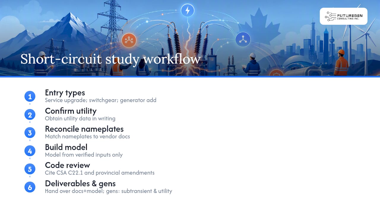
Short circuit studies that reach Futuregenconsulting typically arrive at one of three project stages: a service upgrade where the utility has notified the owner of increased available fault current, a switchgear replacement project where the existing interrupting ratings are unknown or suspect, or a generator addition where the new source contribution has not been quantified. In each case, the starting point is the same: confirm the utility data in writing, reconcile all transformer and switchgear nameplates against vendor documentation, and build the model from verified inputs rather than assumptions.
The firm’s approach to code-first validation means that every study basis cites the applicable edition of CSA C22.1 and the provincial amendments in force for the project jurisdiction (Ontario or Alberta). Model outputs are reviewed against Rule 14-012 device rating obligations before any equipment specification is issued. Deliverables include the full documentation set described above, with model files handed over in the native software format so the owner’s team or a future consultant can re-run the study if conditions change.
For projects involving emergency power systems or generator-connected distribution, the study scope extends to include generator subtransient contributions and, where applicable, coordination with the utility interconnection protection requirements.
Futuregenconsulting’s short-circuit study services for Ontario and Alberta projects

Futuregenconsulting delivers engineer-stamped short circuit studies for commercial and industrial projects in Ontario and Alberta, covering the full workflow from utility data collection through fault calculations, protective device duty evaluation, and arc flash study integration. The firm’s electrical engineers hold working knowledge of CSA C22.1:24 and provincial code amendments, and every deliverable is structured to support procurement, commissioning, and AHJ submission without requiring additional interpretation by the owner’s team.
For projects where study results identify equipment deficiencies, Futuregenconsulting can extend the scope to include electrical construction cost estimation for the recommended upgrades, giving project managers a defensible budget figure tied directly to the study findings. Power system studies, including short-circuit analysis, protection coordination, and arc flash assessment, are available as standalone engagements or as part of a full MEP design scope.
Contact Futuregenconsulting to discuss your project’s scope, confirm typical engagement timelines, and receive a deliverable format that meets your procurement or AHJ requirements.
Sources
The following references should be cited in the study basis of design and consulted for methodology and code compliance:
- CSA C22.1:24, Canadian Electrical Code, Part I, Safety Standard for Electrical Installations
- IEEE Recommended Practice for Conducting Short-Circuit Studies and Analysis of Industrial and Commercial Power Systems
- Short Circuit Analysis Guide
- Guide to the Canadian Electrical Code, Part I (26th Edition) – A Road Map: Section 14 – Protection and Control – Electrical Industry News Week