
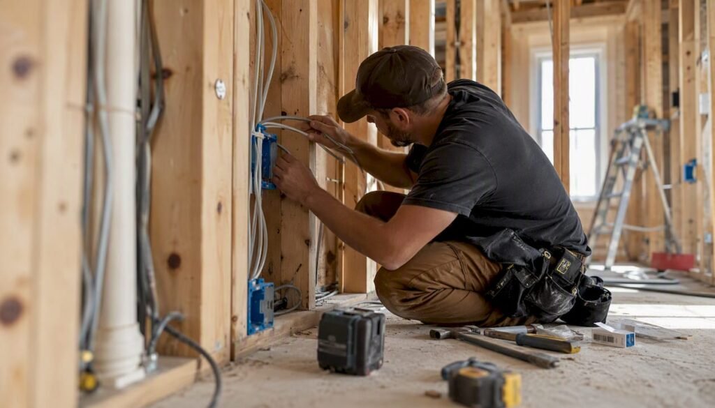
Before a single sheet of drywall goes up, your electrical rough-in must pass an Electrical Safety Authority (ESA) inspection. This inspection-ready electrical rough-in checklist, compiled and reviewed by FutureGen Consulting engineers and mapped directly to ESA inspection criteria, covers every item Ontario inspectors verify before authorizing concealment. Use it on-site, print it, and correct defects before the inspector arrives.
Highest-risk items inspectors always check:
- Cables installed, strapped, and supported at correct intervals
- Outlet boxes installed, securely fastened, and correctly positioned
- Outer cable jackets removed and terminated inside boxes
- Bonding connections completed at all outlet boxes and equipment
- All joints and splices finished and accessible
- Nail and screw protection plates installed where required
- Wiring not concealed until the inspector authorizes concealment
- All OESC-required devices roughed-in and present
- All electrical equipment carrying valid approval for use in Ontario
Stop work immediately if any wiring has been concealed without authorization. Contact ESA to request a rough-in inspection, or engage a Licensed Electrical Contracting Business to correct deficiencies before filing. The sections below expand each item with code references, dimension callouts, and a printable template you can bring to the site.
Key Takeaways
Passing an Ontario electrical rough-in inspection requires verified bonding, correct cable support, accurate box fill, physical protection, and no concealment before authorization.
| Point | Details |
|---|---|
| No concealment before authorization | Concealing wiring before ESA authorizes it is an automatic inspection failure requiring costly rework. |
| Bundle service and rough-in inspections | ESA often combines these for new installations; coordinating them avoids duplicate inspection fees. |
| Calculate box fill before selecting boxes | Use the OESC volume allowance method for every box; overcrowded boxes are a leading re-inspection cause. |
| Test and document before the inspector arrives | Record continuity, insulation resistance, and polarity results by circuit ID and keep copies at the panel. |
| Futuregenconsulting for inspection-ready designs | FutureGen provides engineer-stamped drawings, ESA plan review support, and field reviews for Ontario projects. |
Table of Contents
- What is a rough-in inspection and when does it happen?
- What permits and planning do you need before rough-in?
- What do inspectors check at the service entrance and main panel?
- How should you route and support branch-circuit wiring?
- How do you calculate box fill and mount outlet boxes correctly?
- What are the requirements for ceiling boxes and luminaire supports?
- What are the rough-in requirements for specialty circuits?
- How do you verify grounding and bonding before inspection?
- Where are nail plates, GFCI, AFCI, and smoke/CO detectors required?
- What tests should you run before the rough-in inspection?
- What are the most common reasons rough-in inspections fail?
- How to use the printable electrical rough-in checklist
- How Futuregenconsulting compiled and reviewed this checklist
- A practitioner’s perspective on trade coordination at rough-in
- Futuregenconsulting delivers inspection-ready electrical designs for Ontario projects
- Sources
What is a rough-in inspection and when does it happen?
A rough-in inspection takes place after branch circuit wiring and outlet boxes are installed and before any wiring is concealed by insulation, vapor barrier, drywall, or other building materials. According to ESA’s inspection guidance, this is the stage at which an inspector verifies that wiring methods, device placement, and protection measures comply with the Ontario Electrical Safety Code (OESC) before the work becomes inaccessible.
For new residential construction, ESA commonly bundles the service inspection and the rough-in inspection into a single site visit, which reduces scheduling delays and avoids duplicate fees. If the two inspections are not coordinated, separate fees apply. The practical implication: file your notification early, confirm the scope with ESA after submission, and schedule both inspections simultaneously wherever the project timeline allows.
The rough-in inspection is distinct from the final inspection, which occurs after devices, fixtures, and covers are installed. Inspectors at rough-in focus on wiring methods, physical protection, and bonding continuity, not on finished device operation. Understanding that distinction helps you prepare the right documentation and leave the right items accessible.
What permits and planning do you need before rough-in?
Every electrical installation in Ontario requires a notification filed with ESA before work begins. This applies whether the work is performed by a licensed electrical contractor or by a homeowner in an owner-occupied single-family dwelling.
Key pre-rough-in planning requirements:
- Notification filing: Submit a notification to ESA before starting any electrical work. ESA may refuse a notification where fees are unpaid, prior defects remain unresolved, or the applicant is not compliant with Ontario Regulation 570/05 under the Electricity Act, as outlined in the 2024 OESC amendments.
- Plan review triggers: Certain installations require mandatory plan review before work proceeds, including high-capacity services, electric vehicle supply equipment (EVSE) beyond specific thresholds, and emergency power systems. Confirm whether your project triggers this requirement with ESA or a qualified engineer before starting.
- Who may perform the work: ESA confirms that homeowners may legally perform electrical work in owner-occupied single-family dwellings in Ontario, provided they file a notification and comply with the OESC. For all other property types, a Licensed Electrical Contracting Business must perform the work. ESA recommends engaging a licensed contractor for complex installations regardless of ownership status.
- Drawings and documentation: Projects triggering plan review require engineer-stamped drawings submitted to ESA before inspection. Engaging an MEP engineer early, particularly for service upgrades or specialty circuits, reduces the risk of refusal or re-inspection. For budgeting guidance, electrical construction cost estimation resources can help project owners scope professional fees before committing.
Pro Tip: Schedule your service inspection and rough-in inspection together. ESA often bundles these for new installations, and coordinating them in a single visit avoids the additional fees that apply when they are booked separately.
What do inspectors check at the service entrance and main panel?
Service entrance and main panel items are frequently inspected alongside the rough-in, particularly for new construction. Inspectors verify physical installation, clearances, and documentation at this stage.
Service entrance and panel checklist:
- Service mounting: Confirm the service entrance conductors are properly supported and protected from physical damage at the point of entry. Weatherhead height and clearances from windows, doors, and grade must comply with OESC requirements.
- Meter and main disconnect: The meter base must be securely mounted, and the main disconnect must be accessible, clearly labeled, and rated for the service size. For guidance on sizing and upgrade requirements, the electrical service upgrade guide for Ontario covers OESC thresholds in detail.
- Grounding electrode conductor: The grounding electrode conductor must be correctly sized, routed without splices where required, and connected to an approved grounding electrode system. Verify that all clamps are listed for the conductor type and electrode material.
- Panel location and working clearance: The main panel must be located in an accessible, dry location. OESC requires a minimum working clearance in front of the panel; confirm the specific dimension for your panel voltage rating and verify that no obstructions fall within that zone.
- Panel mounting: The panel must be securely fastened to the structure, plumb, and free of physical damage. Knockouts must be sealed where conductors do not pass through.
- Conductor types and labeling: Conductors entering the panel must be of an approved type for the installation, correctly sized for the service ampacity, and labeled where required. Non-approved conductor types are an immediate failure point.
Service and grounding items, including the meter, main disconnect, and grounding electrode conductor, are part of the service inspection that ESA commonly combines with the rough-in for new installations. Verify grounding electrode installation and bonding continuity before the inspector arrives.
How should you route and support branch-circuit wiring?
Branch-circuit wiring is where most rough-in defects originate. Inspectors examine cable type, support intervals, routing through framing, and how conductors terminate at boxes. Getting these details right before the inspection eliminates the most common re-inspection triggers.
Branch-circuit wiring checklist:
- Cable type: For residential branch circuits in Ontario, NMD90 (non-metallic sheathed cable rated 90°C) is the standard cable type for interior dry locations. Armored cable (AC90) or conduit systems are required where physical protection is needed, such as in unfinished basements, garages, or exposed locations. Confirm the cable type is appropriate for the installation environment.
- Conductor sizing: Wire gauge must match the circuit breaker rating and the load it serves. 14 AWG conductors are typically protected by 15 A breakers; 12 AWG by 20 A breakers. Refer to the OESC and CEC for sizing tables applicable to your specific installation, including temperature correction factors.
- Support and strapping intervals: NMD90 cable must be supported and strapped at intervals not exceeding those specified in the OESC, and within a defined distance of each box. Cables running through bored holes in framing members are considered supported by the framing, but cables running along framing faces require strapping at code-specified intervals.
- Routing through framing: Cables bored through studs must pass through the center of the stud where possible. Where the cable passes within a specified distance of the face of a framing member, a steel protection plate (nail plate) is required. Cables must not be kinked, compressed, or damaged at any point.
- Bushings and penetrations: Where cables pass through metal framing, sharp edges, or conduit fittings, approved bushings or grommets must be installed to prevent abrasion of the cable jacket.
- Conductor termination: At each box, the cable jacket must be removed and terminated inside the box. Conductors must extend a minimum length beyond the box face to allow proper device connection. The OESC specifies the minimum free conductor length at outlets.
- Visibility for inspection: All wiring must remain fully visible and accessible at the time of inspection. No insulation, vapor barrier, or drywall may be installed until the inspector authorizes concealment.
Pro Tip: Photograph each wall cavity before framing is complete. Time-stamped photos showing cable routing, strapping locations, and nail plate installations give inspectors confidence and provide a record if questions arise later.
How do you calculate box fill and mount outlet boxes correctly?
Box fill is one of the most frequently cited defects at rough-in. Overcrowded boxes create heat buildup and increase the risk of insulation damage. The OESC specifies a volume allowance for each conductor, device, and fitting inside a box, and the total must not exceed the box’s rated volume.
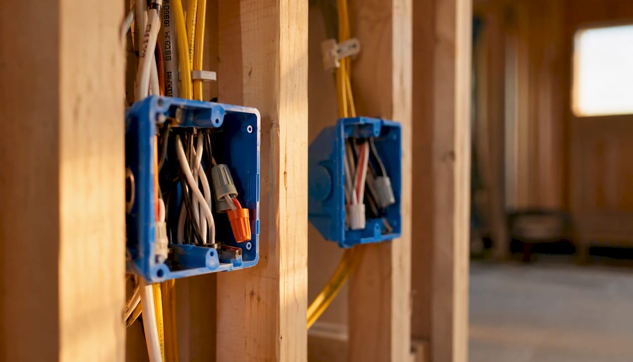
Box fill calculation example:
A standard single-gang plastic box rated at 18 cubic inches (in³) with the following contents:
- Three 14 AWG conductors entering the box: 3 × 2 in³ = 6 in³
- One device (receptacle or switch): 2 × 2 in³ = 4 in³ (counts as two conductors)
- One equipment grounding conductor (all grounds count as one): 1 × 2 in³ = 2 in³
- Total: 12 in³, within the 18 in³ box rating.
Add a cable clamp inside the box, and the clamp counts as one additional conductor equivalent. Always calculate before selecting the box size, not after.
Box mounting and device lead length checklist:
- Boxes must be securely fastened to framing or an approved support bracket, with no movement when moderate force is applied.
- Box face must be flush with or no more than the OESC-permitted setback from the finished wall surface. For combustible surfaces, the box face must be flush or project beyond the surface.
- Device lead length (free conductor length) must meet the OESC minimum at each outlet, typically 150 mm (approximately 6 inches) beyond the box face.
- All boxes must be marked with their rated volume where required by the OESC.
- Boxes must not be installed in locations where they will be inaccessible after construction is complete.
Pro Tip: Coordinate box locations with the framing crew before studs are sheathed. A box placed 25 mm off-center from a stud can conflict with cabinet hardware, tile backer, or trim — relocating it after drywall costs far more than marking the correct position during framing.
What are the requirements for ceiling boxes and luminaire supports?
Ceiling boxes and luminaire supports carry weight and must be rated for the fixture they will hold. An unsupported or under-rated ceiling box is a safety hazard and an automatic inspection failure.
Ceiling box and luminaire support checklist:
- Box rating: Ceiling boxes must be rated for the weight of the luminaire they support. Standard plastic ceiling boxes are typically rated for fixtures up to 23 kg (50 lbs) when properly fastened to framing. Heavier fixtures require a fan-rated box or an independently supported brace bar rated for the specific load.
- Fan-rated boxes: Where a ceiling fan will be installed, the box must be explicitly rated for fan use. A standard luminaire box is not rated for the dynamic load of a rotating fan, even if the static weight is within its limit.
- Independent bracing: Where a box cannot be fastened directly to a framing member (for example, between joists), an adjustable brace bar rated for the fixture weight must be installed between joists. The brace must be secured to solid framing, not to drywall or sheathing alone.
- Swag and pendant suspensions: Pendant fixtures suspended by a cord or chain must have the cord or chain attached to a listed swag hook or canopy rated for the fixture weight. The box itself must still be rated for the load.
- IC-rated fixtures: Where recessed luminaires are installed in insulated ceilings, the fixture must carry an IC (insulation contact) rating. Non-IC fixtures must maintain a clearance from insulation as specified by the manufacturer and the OESC. The IC rating must be visible on the fixture label for inspector verification.
- Temporary supports: During rough-in, ceiling boxes must be secured in their final position. Temporary supports that will be removed before inspection are not acceptable; the box must be in its permanent mounting configuration when the inspector arrives.
What are the rough-in requirements for specialty circuits?
Kitchens, laundry rooms, EV charging stations, and HVAC equipment each carry specific rough-in requirements beyond standard branch-circuit rules. Missing a dedicated circuit or an equipment approval at rough-in typically means a re-inspection.
Specialty circuit rough-in checklist:
- Electric ranges and ovens: Require a dedicated 240 V circuit, typically 40 A or 50 A depending on the appliance rating. The outlet must be located within the appliance’s cord reach and must not be concealed behind the appliance in a way that prevents disconnection.
- Clothes dryers: Require a dedicated 240 V, 30 A circuit with a 4-wire outlet (two hots, neutral, and ground) per current OESC requirements. Confirm the outlet type and location with the appliance manufacturer’s specifications.
- Kitchen countertop receptacles: The OESC requires receptacles spaced so that no point along a countertop is more than 900 mm (approximately 36 inches) from a receptacle. Small appliance circuits serving countertops must be dedicated 20 A circuits; at least two are required in a standard kitchen.
- EVSE (EV chargers): Electric vehicle supply equipment installations may trigger plan review requirements under the OESC, particularly for higher-capacity Level 2 chargers. Confirm the notification and plan review requirements with ESA before rough-in. The circuit must be sized for the EVSE unit’s rated ampacity, and the equipment must carry approval for use in Ontario.
- HVAC equipment disconnects: Dedicated circuits for air conditioning units, heat pumps, and furnaces must include a local disconnect within sight of the equipment. The disconnect must be rated for the equipment’s ampacity and voltage. Confirm equipment approval markings are present and visible.
- Large appliance outlet placement: Outlets for dedicated appliances must be positioned so the appliance cord does not pass through walls, floors, or cabinetry. Placement must allow the appliance to be disconnected without moving adjacent fixtures.
For projects involving EVSE infrastructure or complex HVAC electrical design, plan-review thresholds in the OESC can trigger mandatory engineered drawings and additional approvals, as noted in the 2024 OESC amendments.
How do you verify grounding and bonding before inspection?
Grounding and bonding continuity is one of the items inspectors test at rough-in. Incomplete bonding at outlet boxes or equipment is a common defect that requires rework after drywall, making it one of the most expensive mistakes to correct late.
Grounding and bonding checklist:
- Equipment grounding conductors (EGC): Every branch circuit must include an EGC routed with the circuit conductors. The EGC must be connected at the panel and at each outlet box, device, and piece of equipment on the circuit.
- EGC sizing: The EGC must be sized in accordance with the OESC based on the rating of the overcurrent device protecting the circuit. Refer to the applicable OESC table for the correct minimum size. For a detailed code reference, the grounding and bonding guide for electricians maps OESC requirements to field practice.
- Bonding at outlet boxes: Metal outlet boxes must be bonded to the EGC using an approved bonding means, such as a listed bonding screw or bonding jumper. Plastic boxes do not require bonding, but the EGC must still be connected to any metal device installed in the box.
- Bonding jumpers: Where the EGC is not continuous through a fitting or enclosure, a bonding jumper of the correct size must bridge the gap. Verify that all bonding jumpers are installed and connected before inspection.
- Grounding electrode system: The grounding electrode conductor must connect the service neutral to the grounding electrode system (ground rod, water pipe, or other approved electrode). Connections must use listed clamps appropriate for the electrode and conductor material.
- Coordination with other trades: Where metal water piping or gas piping is required to be bonded under the OESC, coordinate with the plumbing and gas trades to confirm those bonds are installed before the rough-in inspection. An inspector may check for these bonds even if they are not strictly part of the electrical rough-in scope.
Pre-test continuity of all EGCs with a low-resistance ohmmeter before the inspector arrives. Document the results and keep them accessible at the panel.
Where are nail plates, GFCI, AFCI, and smoke/CO detectors required?
Physical protection and device-location requirements are among the most frequently missed items at rough-in. Each of the following categories has specific OESC rules that inspectors verify before authorizing concealment.
Protection and safety device checklist:
- Nail and screw protection plates: Steel protection plates are required wherever a cable passes within 32 mm (approximately 1.25 inches) of the face of a wood framing member, including studs, top plates, and bottom plates. Plates must cover the full width of the cable and be of sufficient gauge to resist penetration by a standard fastener.
- GFCI protection locations: Ground fault circuit interrupter (GFCI) protection is required by the OESC at receptacles in bathrooms, garages, outdoors, kitchens within 1.5 m of a sink, unfinished basements, and other specified wet or damp locations. At rough-in, confirm that the circuit feeding each of these locations is identified and that GFCI protection will be provided either at the receptacle or at the panel.
- AFCI protection locations: Arc fault circuit interrupter (AFCI) protection is required for branch circuits supplying receptacles in bedrooms and, under current OESC requirements, in additional living areas. Confirm AFCI breakers are specified for the correct circuits at the panel rough-in stage.
- Circuit labeling: Circuits requiring GFCI or AFCI protection must be labeled at the panel. Inspectors verify that labeling is present and accurate.
- Smoke detector wiring: Interconnected smoke detectors are required in Ontario dwellings. At rough-in, the wiring for each detector location must be in place, with conductors terminated and accessible. Detectors must be located in each bedroom, outside each sleeping area, and on each floor, including the basement. For life-safety wiring requirements in larger projects, the fire alarm system design guide for Ontario provides additional context.
- CO detector wiring: Carbon monoxide detectors are required in Ontario dwellings that contain a fuel-burning appliance, attached garage, or solid-fuel-burning appliance. Wiring must be roughed-in at the required locations before concealment.
- Documentation for inspectors: Prepare a circuit schedule that identifies each circuit’s GFCI/AFCI status and the location of smoke and CO detector rough-in points. Providing this document to the inspector at the start of the visit reduces the time spent tracing circuits on-site.
What tests should you run before the rough-in inspection?
Running a structured test sequence before the inspector arrives confirms that wiring is correct and gives you documented results to present on-site. Dead tests (with circuits de-energized) come first; live tests follow only where required and safe.
Recommended rough-in test sequence:
- Continuity of protective conductors: Using a low-resistance ohmmeter, verify continuity of the equipment grounding conductor from each outlet box back to the panel. Record the resistance value for each circuit.
- Ring final continuity (where applicable): For ring circuits, verify continuity of both the line and neutral conductors around the ring. This test confirms no open conductors exist before concealment.
- Insulation resistance: Using a calibrated insulation resistance tester (megohmmeter), test each circuit between line and neutral, line and ground, and neutral and ground with the circuit de-energized and all devices disconnected. OESC-compliant installations should show insulation resistance well above the minimum threshold specified in the applicable standard. Record the test voltage used and the measured resistance.
- Polarity verification: Confirm that line and neutral conductors are connected to the correct terminals at each outlet location. Reversed polarity at rough-in is correctable before devices are installed; after drywall, it requires opening walls.
- Earth fault loop impedance (where applicable): Where the installation is energized for testing, measure earth fault loop impedance to confirm that the overcurrent device will operate within the required time under fault conditions.
- Visual inspection of all connections: Before recording final test results, conduct a visual pass of every accessible junction, splice, and termination to confirm that connections are mechanically secure and that no bare conductors are exposed outside of boxes.
Test record template:
Pro Tip: After testing, label each circuit breaker with the circuit ID and tape a copy of the test results inside the panel door. Inspectors can verify results without tracing conductors, which shortens the inspection visit and reduces the chance of a re-inspection request.
What are the most common reasons rough-in inspections fail?
The following defects account for the majority of re-inspections in Ontario residential projects. Correcting them before the inspector arrives is far less costly than scheduling a second visit.
Common defects, ranked by re-inspection frequency:
- Concealed wiring without authorization: The single most costly defect. ESA explicitly warns that concealing wiring before an inspector authorizes it is an automatic failure point. Any insulation, vapor barrier, or drywall installed before inspection requires removal before the inspection can proceed.
- Missing or incomplete bonding: EGCs not connected at boxes or equipment, missing bonding jumpers, or bonding conductors of incorrect size. Fix: trace each circuit from panel to outlet and verify EGC continuity with an ohmmeter before inspection.
- Improper box fill: Too many conductors in an undersized box. Fix: calculate box fill for every box using the OESC volume allowance method and replace undersized boxes before inspection.
- Missing nail and screw protection plates: Cables within 32 mm of a framing face without a steel plate. Fix: walk every stud bay and top/bottom plate with a tape measure and install plates wherever the cable is within the required distance.
- Incorrect cable support intervals: Cables not strapped at required intervals or within the required distance of boxes. Fix: add straps and verify spacing against OESC requirements before the inspector arrives.
- Unapproved equipment: Devices, fixtures, or panels without valid Canadian approval markings (CSA Group, cUL, or equivalent). Fix: replace non-approved components with listed equipment before inspection. The CSA Group certification mark is the most common approval indicator for electrical equipment in Ontario.
- Jacket not terminated in box: Cable jacket ends outside the box rather than inside. Fix: re-terminate all cables so the jacket enters the box by at least 6 mm and is secured by the cable clamp or connector.
Pre-inspection fix checklist for crews:
- Walk every circuit from panel to outlet and verify strapping, nail plates, and jacket termination.
- Calculate box fill for every box and confirm no box is over-filled.
- Test EGC continuity on every circuit and document results.
- Confirm no insulation, vapor barrier, or drywall is installed anywhere on the project.
- Verify all equipment carries a valid Ontario approval marking.
How to use the printable electrical rough-in checklist
The printable rough-in checklist is structured to be completed on-site, room by room, before the ESA inspector arrives. It functions as both a pre-inspection verification tool and a permit record that can be retained for insurance and resale documentation.
What the printable checklist contains:
- Project information block: Property address, permit/notification number, contractor or homeowner name, ESA inspector contact, and inspection date.
- Per-room checklist rows: Each room or circuit zone has its own row covering cable type, support/strapping, box fill calculation, nail plate locations, bonding verification, and device lead length.
- Tests and results section: Fields for recording continuity, insulation resistance, and polarity test results by circuit ID, with space for tester name and date.
- Inspector notes area: A blank field for the inspector to record observations, authorization to conceal, or required corrections.
- Equipment approval log: A column to record the approval marking (CSA, cUL, or equivalent) for each major device or panel component.
How to use it on-site:
Complete the project information block before the inspector arrives. Work through each room systematically, checking off items as you verify them physically, not from memory. Record test values in the tests section immediately after testing, not at the end of the day. Save a digital copy (PDF) to your project file and retain the signed paper copy with your permit records. ESA issues a Certificate of Acceptance after approved inspections; store that certificate with the checklist in your project file.
The checklist is accessible on a mobile device for field use. Where a tablet or phone is used on-site, ensure the PDF is saved locally, not only in cloud storage, to maintain access in areas with limited connectivity.
How Futuregenconsulting compiled and reviewed this checklist
This checklist was compiled and reviewed by FutureGen Consulting engineers with over 30 years of MEP engineering experience in Ontario residential and commercial projects. The content is mapped to the nine inspection items published in the ESA rough-in inspection guidance and cross-referenced against the 2024 OESC amendments and ESA notification requirements.
Compilation methodology and credentials:
- Cross-referenced ESA inspection guidance, OESC amendment documents, and field experience from residential and commercial MEP projects across Ontario.
- Mapped each checklist item to the specific ESA inspection criterion it addresses, so installers and inspectors can trace every requirement to its regulatory source.
- Reviewed for consistency with the Ontario Electrical Safety Code as amended through 2024 and with CSA Group certification requirements applicable in Ontario.
- Verified against common re-inspection defects observed during field reviews on Ontario projects.
Important disclaimer: This checklist provides general guidance mapped to publicly available ESA and OESC requirements. It does not replace project-specific engineering advice, and acceptance at inspection does not shift legal responsibility for OESC compliance from the owner or contractor. As ESA clarifies, an inspection does not replace the requirement to comply with the OESC; the owner and contractor remain responsible for full code compliance regardless of inspection outcome. For projects that trigger plan review, involve high-capacity services, EVSE infrastructure, or emergency power systems, engage a licensed MEP engineer before filing your notification. Inspections are project-specific, and the scope an inspector covers depends on the filed notification, so always confirm expected coverage with ESA after submitting.
A practitioner’s perspective on trade coordination at rough-in
The most preventable rough-in failures have nothing to do with code knowledge. They come from trades working in sequence rather than in parallel, without a shared understanding of where each system runs.
On a typical Ontario residential project, the electrical rough-in crew arrives after framing and before insulation. What they find, consistently, is that HVAC ductwork has already claimed the space where electrical boxes were planned, or that plumbing drain lines run exactly where a cable needed to pass through a top plate. Relocating a box after framing is a minor inconvenience. Relocating it after drywall is a cost that rarely appears in the original estimate.
The fix is straightforward: schedule a pre-rough-in walkthrough with the framing, HVAC, and plumbing trades before any rough-in work begins. Walk the floor plan together, mark conflicts on the framing, and resolve them before anyone pulls wire. On one Ontario renovation project reviewed by FutureGen engineers, a single 30-minute coordination walkthrough identified four box locations that conflicted with supply ductwork and two cable routes that would have required re-boring through a structural beam. Resolving those conflicts before rough-in saved an estimated two days of rework.
Electrical contractors who build this coordination step into their standard pre-installation process consistently report fewer re-inspections and fewer change orders. The Electrician’s SWOT analysis framework published by MOGHQ identifies trade coordination as one of the highest-leverage operational improvements available to electrical contractors, precisely because its absence creates compounding costs across every subsequent trade.
Futuregenconsulting delivers inspection-ready electrical designs for Ontario projects
Passing a rough-in inspection on the first visit requires more than a checklist. It requires permit-ready drawings, accurate load calculations, and documentation that maps every circuit to its OESC requirement before the inspector arrives.

Futuregenconsulting provides MEP engineering design services for residential and commercial projects across Ontario, including ESA plan review support, engineer-stamped electrical drawings, and field review services that identify deficiencies before they become re-inspection costs. For developers, contractors, and property managers who need inspection-ready documentation without the back-and-forth of a re-inspection cycle, FutureGen’s MEP engineering services deliver permit-ready packages aligned to current OESC requirements and ESA plan review standards. For projects involving electrical engineers in home renovations, the role of electrical engineers in residential projects explains when engineering engagement is required and what it delivers. Contact Futuregenconsulting to request a pre-inspection review or to engage engineering design services for your next Ontario project.
Sources
The following sources provide binding requirements and official guidance for electrical rough-in work in Ontario. Consult them directly for project-specific requirements, as code obligations vary by installation type, service size, and notification scope.
- Prepare for Your Inspection – Rough in Inspection (ESA PDF)
- Do-It-Yourself (DIY) electrical work – ESA
- What is a rough-in inspection and when does it take place? – ESA
File your ESA notification before starting work, confirm the inspection scope with ESA after submission, and consult the OESC directly for binding requirements applicable to your specific installation.