
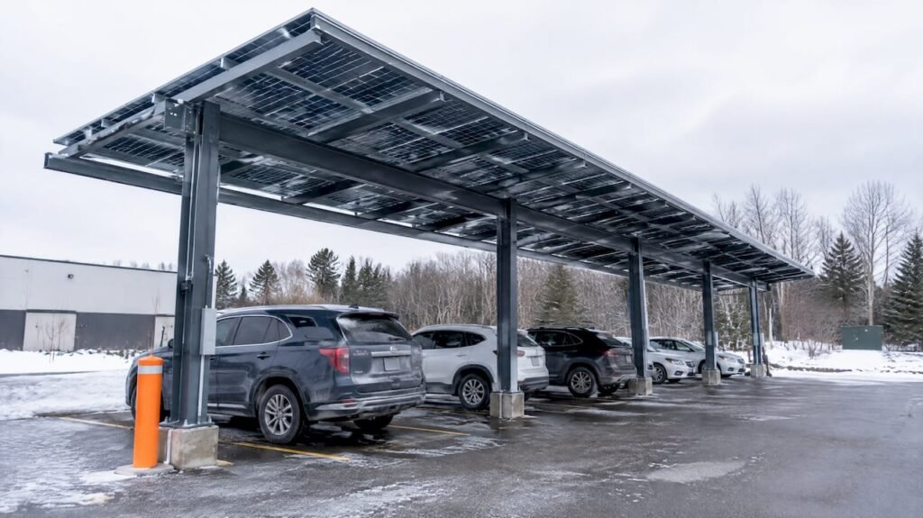
A safe, durable solar carport starts with integrated structural and electrical design, paired with early utility engagement, because skipping those steps risks delays, rework, or outright project failure. The foundation must match local frost depth and snow loading, the electrical design must satisfy Electrical Safety Authority review triggers, and the local distribution company needs a seat at the table before equipment gets ordered. Start now with a site shading survey and a call to your local distribution company, then bring in a structural and electrical engineer before you finalize a layout.
TL;DR:
- Ensuring proper site shading analysis and early utility engagement prevents costly rework and delays during project development.
- Foundation design must consider regional frost depth and soil conditions to avoid frost heave and maintain long-term structural integrity.
- Electrical systems require compliance with safety codes and early coordination with the electrical distributor to prevent equipment mismatches or upgrades.
- Snow and wind loads significantly influence structural design, connection details, and the choice of pitch to balance snow shedding and wind uplift resistance.
- Integrating structural, electrical, and civil engineering from the start reduces conflicts, streamlines permitting, and supports comprehensive project coordination.
Table of Contents
- Planning and site assessment: solar access, program needs, and stakeholder contacts
- Structural design: canopy geometry, pitch, wind and snow loading, and deliverables
- Foundations and site geotechnical factors
- Electrical design, permitting, and interconnection
- Installation and commissioning: sequencing, tests, and acceptance
- Operations and maintenance: snow clearing, monitoring, and lifecycle tasks
- Integrated MEP perspective and what to ask a consulting engineer
- Lighting considerations for the carport area to ensure safe usage at night
- Stormwater runoff management related to carport structures
- Accessibility and user experience design elements
- Detailed cable management and wiring best practices
- Fire safety standards and compliance specific to solar carports
- Integration with energy storage systems and potential design modifications
- What experience on these projects actually teaches
- How FutureGen Consulting supports your solar carport project
- FAQ
- Sources
Planning and site assessment: solar access, program needs, and stakeholder contacts
Every solar carport design begins with a solar access study. We record shading obstructions, sun path angles across seasons, and azimuth orientation using irradiance modeling tools, then translate that data into array tilt, row spacing, and string layout decisions. A site that looks open in July can lose a meaningful share of winter production to a low sun angle behind a tree line or an adjacent building.
Program needs come next: how many parking stalls need covering, whether Level 2 or DC fast EV chargers share the structure, and what annual energy output the owner expects. These numbers set the footprint and the required module count, which in turn drives post spacing and canopy width.
Orientation and pitch involve trade-offs. A steeper pitch sheds snow faster and drains better, but it increases wind uplift forces and changes the sightlines drivers need under the canopy.
- Confirm solar access with a shading study before committing to array layout
- Define parking count, EV charging needs, and energy targets early
- Balance pitch against drainage, snow shedding, and wind exposure
- Contact your local distribution company and authority having jurisdiction before design finalization, since Electrical Safety Authority plan review applies above certain generation thresholds
Early contact with the local distribution company and the Electrical Safety Authority (ESA) avoids a design that later needs rework to satisfy interconnection or permitting rules.
Structural design: canopy geometry, pitch, wind and snow loading, and deliverables
Pitch choice is not purely aesthetic. A shallow roof sheds snow slowly, which raises the design snow load the structural engineer must carry, while a steep pitch reduces snow retention but increases the wind uplift the connections need to resist. Both forces get combined under Canadian structural codes to size posts, beams, and footings.
Concentrated snow loads matter more on carports than on typical roofs, since snow sliding from an adjacent building or drifting against a canopy edge can pile well beyond the uniform design load. Wind uplift governs most connection designs on open structures like carports because there is no enclosed building mass resisting the pressure differential across the panel surface.
- Confirm ground snow load and wind pressure values for the project location from the applicable provincial building code
- Size primary structural members (posts, beams, purlins) for combined dead, snow, and wind load cases
- Detail connections for uplift resistance, not just gravity loads
- Set row spacing to avoid inter-row shading while keeping clear vehicle height
- Confirm racking manufacturer load tables match the site’s climate data
- Issue stamped structural drawings, including connection details and foundation reactions, for permit submission
Pro Tip: Ask your structural engineer to model both uniform and drifted snow cases separately, since the drifted case often governs connection design even when the uniform load looks manageable.
Required structural deliverables include load calculations, a stamped general arrangement drawing, connection detail sheets, and foundation reaction tables that the geotechnical or civil engineer needs to size footings. A Professional Engineer’s stamp on these drawings is what most Canadian municipalities require before issuing a building permit for a carport of meaningful span.
Foundations and site geotechnical factors
Foundation choice depends on soil conditions, frost depth, and load magnitude. Driven piles work well in sandy or loose soils where mechanical driving is practical; drilled piers suit sites with variable soil layers or where precise depth control matters; spread footings fit shallow installations on stable, well-drained ground with lighter structural loads.
Frost penetration depth changes everything about embedment. In milder coastal or southern regions, frost lines run shallower than in northern climates, and Ontario building guidance notes that frost depth varies materially by region, which changes required pier or pile depth and can significantly shift foundation cost between a mild site and a cold-climate one. A foundation that ignores local frost depth risks frost heave, post movement, and long-term racking misalignment.
- Match foundation type to soil conditions and load magnitude, not just cost
- Confirm local frost depth with the authority having jurisdiction before sizing piers
- Commission a geotechnical report for larger installs or unusual soils; smaller installs may proceed on documented engineering judgment where soils are well understood
- Grade the site to direct water away from post bases and maintain clear access paths
Electrical design, permitting, and interconnection
The electrical design has to satisfy both the Electrical Safety Authority and the local distribution company before the project can connect to the grid. In Ontario, ESA requires plan review submission for installations where electric-power-generating equipment operates in parallel with the supply authority and the rating exceeds 10 kW, and that submission now goes exclusively through the ESA Electronic Plan Review portal rather than paper or email.
Combined systems matter here too: when multiple generation sources are installed at the same time, ESA assesses them by their aggregate rating, so a 7 kW carport array paired with a separate 5 kW rooftop system can trigger plan review even though neither system alone exceeds the threshold.
- Determine whether the combined generation rating exceeds the 10 kW plan review threshold and submit through the ESA Electronic Plan Review portal if it does
- Confirm the connection pathway with the local distribution company: Form C typically applies to micro-generation at or below the micro-generation threshold, while larger installations require Form B and a Connection Impact Assessment
- Secure an Offer to Connect before ordering inverters, transformers, or other major equipment, since the distribution company’s capacity assessment can require upgrades that change the design
- Produce a single-line diagram showing the generator disconnect, isolation switch location, and rapid shutdown provisions
- Mark maximum PV circuit voltage per Rule 64-202, label all PV-specific equipment per ESA bulletin 64-05-4, and coordinate inverter protection settings with any bi-directional EV charging or battery storage sharing the same service
Ordering equipment before the Offer to Connect is confirmed is one of the most common causes of stranded capital on these projects, since the distribution company may require a different inverter size or a grid upgrade once its impact assessment is complete. Our ESA plan review guide and our interconnection timeline reference walk through what each submission path typically requires.
Installation and commissioning: sequencing, tests, and acceptance
Construction generally follows a fixed sequence: civil work and foundations first, then structural framework erection, racking and module mounting, electrical rough-in, and finally the inverter and grid interface connection. Skipping ahead on any stage, particularly ordering racking before foundation design is finalized, tends to create costly field changes.
Commissioning closes the loop before the utility authorizes connection. The checklist typically includes continuity and polarity testing of all circuits, inverter anti-islanding and functional tests, verification of protective device settings against the approved design, and an as-built single-line diagram reflecting any field changes.
- Sequence construction civil too structural to electrical to avoid field rework
- Complete continuity, polarity, and inverter function testing before requesting final inspection
- Keep witness test records and the as-built single-line diagram for the utility and ESA inspector
- Expect final inspection to confirm the isolation switch, labeling, and rapid shutdown provisions match the approved drawings
Late equipment procurement and delayed utility engagement remain the two most common schedule risks on these projects.
Operations and maintenance: snow clearing, monitoring, and lifecycle tasks
A maintenance program for a solar carport needs a regular cadence: visual inspections for racking corrosion or loose hardware, periodic torque checks on structural connections, electrical testing of ground continuity and insulation resistance, and a routine review of production monitoring data against expected output.
Design choices made early pay off here. Sufficient pitch and planned access corridors between rows make snow clearing faster and reduce the chance of a maintenance crew needing to work under an energized array in poor footing conditions.
- Schedule visual and torque inspections at least annually, more often in heavy snow regions
- Post signage identifying energized circuits and disconnect locations for maintenance crews
- Use remote monitoring to flag underperforming strings before a site visit is needed
Pro Tip: Set production alerts at the string level rather than the array level, since a single shaded or failed string often goes unnoticed in whole-array totals until the seasonal drop becomes obvious.
Integrated MEP perspective and what to ask a consulting engineer
Projects that separate structural, electrical, and civil design into disconnected contracts tend to discover conflicts late, typically when racking attachment points do not match the foundation layout or when the electrical single-line diagram gets drawn after the structural permit is already submitted. An integrated mechanical, electrical, and plumbing design approach catches these conflicts before they reach the field.
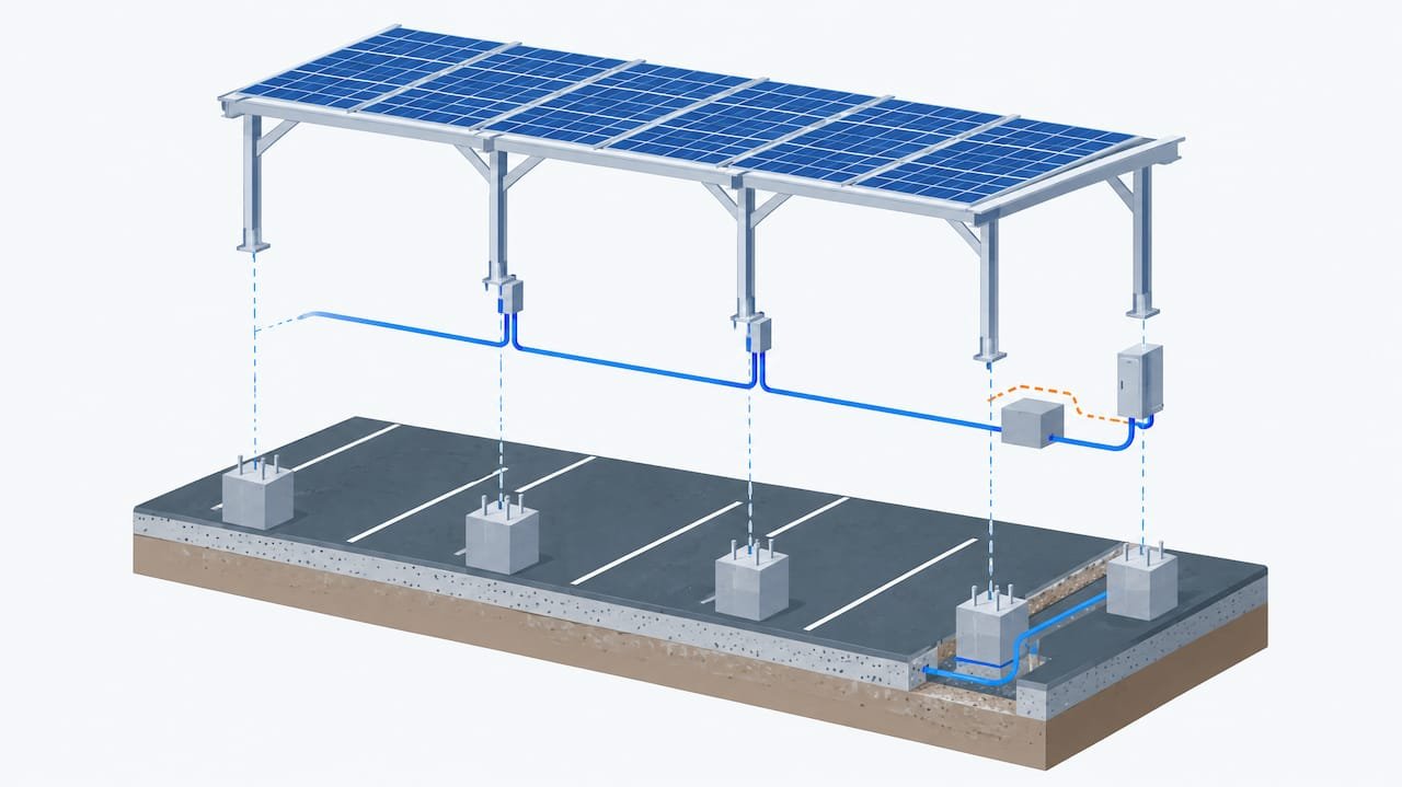
A minimum deliverable set from a consulting engineer should include a site survey, stamped structural and electrical drawings, a single-line diagram, and support through the ESA plan review submission. A team bringing solar power system design, power distribution, and EV charger infrastructure design under one engineering scope keeps those disciplines coordinated from the first site visit. Before approving major equipment purchases, confirm the Offer to Connect review is complete.
Lighting considerations for the carport area to ensure safe usage at night
Lighting design under a solar carport has to balance two needs: enough illumination for safe pedestrian and vehicle movement at night, and a fixture layout that does not conflict with the racking structure or shade the array during the day. LED fixtures mounted to the underside of the canopy framework are the common approach, since they avoid separate pole foundations and keep the wiring run short.
Photometric design should target even illumination across parking stalls and walkways without creating sharp light and shadow transitions at the canopy edges, which are a common source of pedestrian trip hazards. Motion sensors or timed dimming can reduce energy draw during low-traffic hours, and that draw can be sized into the same electrical service as the solar array where capacity allows.
Wiring for carport lighting should run in dedicated conduit separate from the PV DC circuits, with clear labeling at the panel to distinguish lighting loads from generation circuits. This separation matters at inspection time, since an inspector checking rapid shutdown or isolation switch locations needs to confirm lighting circuits are not mistaken for PV circuits during an outage or maintenance event.
Fixture selection should account for the carport’s exposure: enclosed, gasketed fixtures resist the moisture and road salt spray common in parking structures, and a photocell or network-based control lets a facility manager adjust schedules without a site visit. Our site lighting design services coordinate fixture placement with the structural layout so lighting conduit runs do not conflict with racking attachment points decided earlier in the design.
Stormwater runoff management related to carport structures
A solar carport changes the drainage pattern of a parking lot, even though the structure itself is open. Rainfall that would otherwise fall directly onto pavement instead sheds off the panel surfaces at the roof pitch angle, concentrating flow at specific drip lines along the canopy edges rather than spreading evenly across the lot.
That concentrated flow can erode pavement joints or create standing water at the drip line if the site grading does not account for it. Grading the parking surface with a slight slope away from post footings, combined with drainage channels or permeable pavement sections beneath the drip line, prevents pooling and reduces long-term pavement damage.
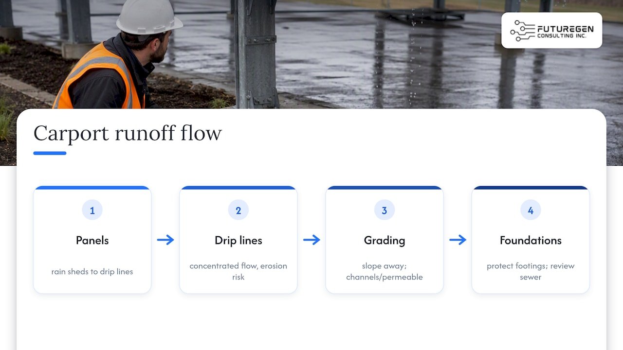
Larger installations, particularly those covering a significant share of a parking lot’s surface area, may need to be reviewed against municipal stormwater management requirements, since a canopy can change how quickly water reaches a storm sewer connection compared with open pavement. Civil engineers typically model this during site design rather than leaving it to be discovered after construction.
Foundation design also intersects with drainage: footings placed in low points of the lot are more exposed to standing water and frost heave risk, so coordinating foundation placement with the grading plan during the civil design stage avoids a maintenance problem that is expensive to fix after paving is complete.
Accessibility and user experience design elements
Parking stall layout under a solar carport has to meet the same accessibility requirements as any other parking facility, including accessible stall width, signage, and proximity to building entrances, while also accounting for the canopy’s post spacing and vehicle clearance height.
Vehicle clearance is a frequent design conflict point. Taller vehicles, including vans and some SUVs, need adequate clearance beneath the lowest point of the structure, which typically means designing the low edge of the canopy pitch with enough margin above the posted clearance height rather than the bare code minimum.
Post placement needs careful coordination with stall striping. Posts set too close to a stall’s edge create a door-opening hazard and complicate accessible stall approach paths, so the structural layout should be reviewed against the parking layout plan before footing locations are finalized rather than after.
Wayfinding and lighting work together here as well: clear sightlines to accessible stalls, consistent illumination, and unobstructed post placement near curb ramps all contribute to a carport that functions well for every driver, not just the majority case.
Detailed cable management and wiring best practices
Cable management under a solar carport has to withstand outdoor exposure, vibration from vehicle traffic below, and temperature swings across seasons, all while remaining accessible for future maintenance or troubleshooting. DC wiring from the modules typically runs within the racking structure using UV-rated conduit or cable trays rated for outdoor use, secured at intervals that prevent sagging or abrasion against structural members.
Home runs from the array to the inverter location should follow the shortest practical path while avoiding areas where vehicles might strike exposed conduit, and all conduit penetrations through structural members need proper sealing to prevent water intrusion into the conduit run. Cable trays or conduit runs should be labeled at regular intervals and at every junction box, identifying voltage and circuit source, which speeds up both inspection and any future fault-finding.
Separating AC and DC wiring runs, and keeping PV circuits separate from EV charger or lighting circuits, is not just good practice, it directly supports the isolation and disconnect requirements inspectors check during final review. A mislabeled or commingled wiring run is one of the more common reasons a project fails first inspection.
Strain relief at every connection point, proper torque on lugs and terminals per manufacturer specification, and drip loops at any vertical-to-horizontal transition all reduce long-term failure risk from thermal cycling and vibration, both of which are more pronounced on an open carport structure than on a roof-mounted system.
Fire safety standards and compliance specific to solar carports
Fire safety considerations for a solar carport center on two issues: keeping emergency responders able to quickly de-energize the system, and preventing the structure or its wiring from becoming a fire propagation path. The accessible, lockable isolation switch required between the meter and the customer’s equipment serves both purposes, giving first responders a known location to disconnect generation during an emergency.
Rapid shutdown provisions, already required for electrical compliance, also serve a fire safety function by reducing shock hazard to firefighters working near or under the array during an incident. Labeling requirements under the applicable ESA bulletins exist specifically so responders can identify PV circuits at a glance rather than treating every conductor as potentially energized.
Clearances between the array and any adjacent building, as well as combustible storage kept clear of the carport’s structural posts, reduce the chance of a vehicle fire or nearby ignition source spreading to the canopy structure. Local fire departments may have specific access requirements for carport installations near a building, particularly where the structure sits close to a fire route or hydrant access path, so confirming those requirements with the authority having jurisdiction during design avoids a late-stage redesign.
Integration with energy storage systems and potential design modifications
Adding battery storage to a solar carport changes both the electrical design and, sometimes, the physical layout. The inverter protection settings need to account for bi-directional power flow if the storage system can both charge from and discharge to the connected loads or the grid, which is a different protection scheme than a simple one-way generation system.
Physically, battery enclosures typically need a dedicated pad or wall-mounted location rather than living inside the carport canopy itself, since most battery products carry clearance, ventilation, and temperature requirements that an open-air carport structure cannot reliably meet. That usually means allocating adjacent ground space or a nearby equipment room during the planning stage rather than treating storage as an afterthought.
Combining storage with the existing generation rating also affects the ESA plan review threshold discussed earlier, since the aggregate rating of generation and storage equipment operating in parallel with the supply authority is what determines whether plan review is required. A carport array under 10 kW paired with a storage system can push the combined rating over that threshold, which changes the permitting path.
Coordinating storage sizing with EV charger load profiles under the same carport is increasingly common, since a battery can offset peak charging demand and reduce the size of utility upgrade otherwise triggered by simultaneous EV charging and building loads. Our EV charger infrastructure design service addresses this load coordination directly when chargers and storage share a carport’s electrical service.
What experience on these projects actually teaches
The most common failure pattern we see is not a structural miscalculation or a wiring error. It is a project that designs the array first and contacts the local distribution company last, then discovers the Offer to Connect requires a different inverter size or a service upgrade after equipment is already ordered. Treat utility engagement and permit planning as parallel tracks from day one, not a final step before construction. Start with a shading study and a call to your distribution company in the same week.
— Sanjay
How FutureGen Consulting supports your solar carport project
Solar power system design, power distribution, and EV charger infrastructure design brought together under one engineering scope keep a carport’s structure, wiring, and interconnection documents coordinated from the first site visit rather than reconciled late.

A first engagement typically includes a site review, stamped structural and electrical drawings, and support through plan review submission, with timelines shaped by the site’s permitting path.
- Solar power system design and single-line diagram preparation
- Power distribution coordination and plan review submission support
- EV charger infrastructure design for carports combining charging and generation
- Electrical construction cost estimation to budget the project accurately
For design teams needing structural thermal or load modeling tools alongside engineering support, the engineering simulation toolkit from Jewlz Technologies offers a practical Excel-based option for early calculations. Reach out through our services page to scope your project.
FAQ
How much does it cost to make a solar carport?
Cost depends heavily on foundation type, span, and local frost depth, since deeper piers in cold-climate regions generally add materially to the budget compared with a shallow-footing site. We do not publish a flat price because scope varies by project; request a quote through our services page once your site assessment is complete.
What is the 20% rule for solar?
There is no single universal “20% rule” recognized across Canadian codes; the phrase is sometimes used informally for setback or coverage guidelines that vary by municipality and utility. Check your authority having jurisdiction and local distribution company directly rather than relying on a generic rule of thumb.
Why are people getting rid of their solar panels?
Panels are typically removed due to end-of-life degradation, roof or structural replacement needs, or a mismatch between original system design and current energy needs rather than any inherent product failure. A well-engineered carport array, sized correctly from the start, reduces the chance of premature removal driven by underperformance.
How do I make a carport with solar panels?
Start with a solar access and shading study, then engage a structural engineer for load calculations and an electrical engineer for the single-line diagram and ESA plan review submission. Foundation work, framework erection, and electrical rough-in follow in sequence, with commissioning tests completed before the local distribution company authorizes final connection.