

Power factor correction is the engineering practice of adding capacitive reactive power to an AC electrical system to compensate for the reactive demand created by inductive loads. Without correction, facilities pay for power they cannot convert into useful work. Alberta’s industrial and commercial sectors, which run heavy motor loads, variable frequency drives (VFDs), and arc furnaces, face measurable financial penalties when power factor falls below utility thresholds. The standard industry target is a power factor of 0.95 or higher. This guide covers the calculation methods, correction equipment, harmonic risks, and economic returns that electrical engineers and facility managers need to make sound decisions.
What is power factor correction and how is it calculated?
Power factor (PF) is defined as the ratio of real power (kW) to apparent power (kVA): PF = kW / kVA. Real power does actual work. Apparent power is the total current demand the utility must supply, including the reactive component that inductive loads draw but do not convert to work. The gap between the two is reactive power, measured in kVAR, and it is the target of any correction program.
The power triangle makes this relationship concrete. Real power (P) forms the horizontal leg, reactive power (Q) forms the vertical leg, and apparent power (S) is the hypotenuse. The angle phi between P and S determines the power factor: PF = cos(phi). A facility running at 0.75 PF has a large phi angle, meaning a large reactive component relative to its real load.

Capacitor bank sizing follows a direct formula: Required kVAR = kW × (tan phi1 – tan phi2), where phi1 is the existing angle and phi2 is the target angle. For a 500 kW load at 0.75 PF corrected to 0.95 PF, the calculation yields approximately 277 kVAR of capacitive compensation. That correction reduces apparent power demand by up to 29%, which directly cuts the kVA billing component on utility invoices.
Correction multiplier reference
| Starting PF | Target PF | Multiplier (× kW = kVAR needed) |
|---|---|---|
| 0.70 | 0.95 | 0.691 |
| 0.75 | 0.95 | 0.553 |
| 0.80 | 0.95 | 0.421 |
| 0.85 | 0.95 | 0.291 |
| 0.90 | 0.95 | 0.159 |
The multiplier method gives a fast field estimate. Always apply a 10–15% safety margin on the calculated kVAR value to account for load variation before specifying equipment.
- Measure real power (kW) and apparent power (kVA) over a full production shift.
- Calculate existing PF and determine the target (typically 0.95–0.98 lagging).
- Apply the kVAR formula to find required capacitor bank size.
- Add a 10–15% margin and select the nearest standard capacitor rating.
- Verify that the selected bank does not push PF above 0.98 at minimum load.
Pro Tip: Never target unity (1.0) PF. Over-correction to unity PF can cause dangerous voltage rises, ferroresonance, and damaging interactions with VFDs. The safe target range is 0.95–0.98 lagging.
What methods and devices are used for power factor improvement?
The two primary categories of power factor correction devices are static (fixed) capacitor banks and automatic power factor correction (APFC) systems. The right choice depends on whether the facility load profile is constant or variable.
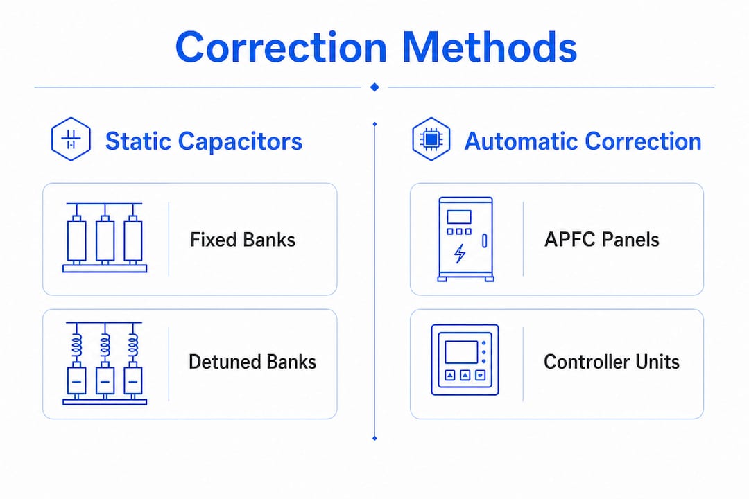
Fixed capacitor banks connect a set kVAR value directly to the bus. They work well for facilities with stable, predictable loads such as pumping stations or constant-speed motor installations. The limitation is that a fixed bank sized for full load will over-correct during light load periods, pushing PF into the leading zone and creating voltage instability.
APFC systems use a real-time PF sensing controller, contactors or thyristor switches, and multiple capacitor steps. The controller monitors PF continuously and switches capacitor steps in or out to maintain the target range. Fixed banks can cause leading PF during low load periods, while APFC panels manage reactive compensation dynamically. This makes APFC the standard choice for manufacturing plants, data centers, and commercial buildings with variable loads.
- Metallised polypropylene film (MPP) capacitors: The industry standard for industrial PFC. MPP capacitors offer up to 100,000 hours of continuous AC duty. A 10% overvoltage increases their reactive output by 21%, so voltage regulation at the installation point is critical.
- Thyristor switching: Provides near-instantaneous step switching with no contact wear, suitable for rapidly fluctuating loads.
- Contactor switching: Lower cost, adequate for loads that change slowly over minutes rather than seconds.
- Synchronous condensers: Rotating machines that supply or absorb reactive power continuously. Used in large utility-scale or heavy industrial applications where stepless control is required.
- Phase advancers: Applied specifically to wound-rotor induction motors to supply reactive current at the rotor circuit, reducing stator reactive demand.
Pro Tip: Install APFC panels at the main low-voltage bus rather than at individual load points. This gives the controller visibility over the full facility load and prevents localized over-correction.
How do harmonics affect capacitor banks and what are the mitigation strategies?
Harmonics are the single most common cause of capacitor bank failure in industrial facilities. Non-linear loads including VFDs, LED lighting systems, arc furnaces, and uninterruptible power supplies (UPS) inject harmonic currents at multiples of the fundamental frequency (5th, 7th, 11th, and higher orders). These currents interact with capacitor banks in ways that can destroy equipment within months of installation.
The core risk is parallel resonance. When the natural resonant frequency of the capacitor bank and the system inductance coincides with a dominant harmonic order, harmonic currents amplify dramatically. The resulting overvoltage and overcurrent stress capacitor dielectric films beyond their rated limits. The most common failure in PFC projects is ignoring harmonics, which results in capacitor damage and increased system instability.
Harmonic mitigation comparison
| Mitigation method | Resonance protection | Harmonic filtering | Typical application |
|---|---|---|---|
| Detuned reactor (7%) | Yes | Partial | General industrial |
| Detuned reactor (14%) | Yes | Stronger | High harmonic environments |
| Passive harmonic filter | Yes | Targeted | Specific harmonic orders |
| Active harmonic filter | Yes | Broadband | Complex, variable loads |
Detuned reactors are the standard engineering solution. Adding 7% or 14% detuned reactors shifts the resonant frequency of the capacitor bank below the 5th harmonic (250 Hz on a 50 Hz system, 300 Hz on a 60 Hz system), preventing destructive amplification. The 7% reactor is appropriate for most industrial environments. The 14% reactor applies where 3rd harmonic content is significant.
Key mitigation practices for Alberta industrial facilities:
- Conduct a harmonic analysis before specifying any capacitor bank.
- Never install capacitor banks at the output terminals of VFDs. Capacitor banks must never be installed downstream of VFDs because capacitive interaction damages drive semiconductors.
- Specify detuned reactors as standard equipment in any facility with non-linear loads exceeding 20% of total load.
- Consider active harmonic filters where load composition changes frequently and passive solutions cannot track the harmonic spectrum.
Pro Tip: Request a power quality survey that covers at least one full production shift, including startup and shutdown sequences. Snapshot measurements often misrepresent load variations, leading to undersized or incorrectly tuned correction systems.
What are the financial and operational benefits of power factor correction?
The financial case for power factor improvement in Alberta is direct and quantifiable. Alberta utilities measure demand in kVA, not kW, for commercial and industrial accounts. A facility operating at 0.75 PF pays for significantly more apparent power than one at 0.95 PF delivering the same real work. A facility moving from 0.5 PF to 0.95 PF can save $3,200 per month in demand penalties alone, with line losses quadrupling at 0.5 PF compared to unity.
Payback periods are short relative to capital cost. Improving power factor from 0.85 to 0.95 delivers payback periods between 6 and 18 months, depending on facility size and utility tariff structure. That timeline makes PFC one of the fastest-returning electrical infrastructure investments available to facility managers.
The operational benefits extend beyond the utility bill:
- Reduced line losses: Lower reactive current means less resistive heating in cables, busbars, and transformer windings. This directly extends insulation life and reduces maintenance frequency.
- Improved voltage stability: Reactive compensation raises voltage at the load bus, reducing voltage drop across feeders. Stable voltage protects sensitive equipment and reduces nuisance tripping.
- Transformer and switchgear capacity gain: Correcting 0.72 PF to 0.95 PF increases transformer effective capacity by over 230 kW. Effective power factor correction can increase available transformer capacity by over 30% without physical upgrades, deferring expensive equipment replacement.
- Extended asset life: Lower operating temperatures in cables and transformers translate directly to longer insulation life and fewer unplanned outages.
- Infrastructure upgrade deferral: Facility managers often overlook the value of PFC in extending asset life and deferring costly infrastructure upgrades. A well-sized capacitor bank can delay a transformer replacement by years.
The combination of penalty avoidance, reduced losses, and deferred capital expenditure makes the financial argument for correction compelling at virtually any facility scale.
Key Takeaways
Power factor correction delivers measurable financial returns and operational gains when sized correctly, harmonics are addressed, and automatic control is applied to variable loads.
| Point | Details |
|---|---|
| Target PF range | Correct to 0.95–0.98 lagging; never target unity to avoid voltage rise and VFD damage. |
| Size with full-shift data | Use a complete production shift survey, not snapshot readings, to accurately size capacitor banks. |
| Always address harmonics | Install detuned reactors (7% or 14%) in any facility with non-linear loads before commissioning capacitor banks. |
| APFC for variable loads | Use automatic power factor correction panels with stepped switching for facilities with fluctuating load profiles. |
| Payback is fast | Correction from 0.85 to 0.95 PF typically returns capital investment within 6–18 months through demand charge savings. |
An engineer’s perspective on power factor correction done right
The facilities that get the most out of power factor correction are the ones that treat it as an engineering project, not a product purchase. I have seen capacitor banks installed based on a single meter reading taken on a Tuesday afternoon, then destroyed by harmonic resonance within six months because nobody checked what the VFDs were doing to the harmonic spectrum. That outcome is entirely preventable, and it sets back the business case for correction by years.
The most important step is the power quality survey. It needs to cover startup, full production, partial load, and shutdown. Load profiles in Alberta’s oil and gas processing facilities, for example, shift dramatically between operational phases. A capacitor bank sized for peak load will over-correct during maintenance windows, and a bank sized for average load will leave penalty charges on the table during peak production.
I advocate strongly for APFC systems in any facility where load varies by more than 20% across a shift. The controller cost is recovered quickly through avoided over-correction penalties and reduced stress on capacitor cells. Fixed banks belong in pump stations and similar constant-load applications, not in process plants.
The harmonic question is non-negotiable. Every project I have worked on with non-linear loads above 20% of total demand has required detuned reactors. Skipping that step to save capital cost is a false economy. The reactor adds perhaps 15–20% to the capacitor bank cost and eliminates the primary failure mode. PFC should be treated as an engineering design project balancing load profile analysis, harmonic control, and equipment selection for long-term reliability.
Finally, do not overlook the power distribution design implications. Where you install the correction bank, whether at the main bus, at individual feeders, or at motor terminals, changes the scope of loss reduction and the complexity of the harmonic analysis. Each location choice has tradeoffs that require engineering judgment, not a catalog selection.
— Sanjay
Futuregenconsulting: professional power factor correction engineering
Futuregenconsulting brings over 30 years of MEP engineering experience to power factor correction projects across commercial and industrial facilities. The firm’s electrical engineering team conducts full power quality surveys, harmonic analysis, and capacitor bank sizing calculations to deliver correction systems that perform reliably over the long term.

Whether your facility needs a fixed capacitor bank for a constant motor load or a fully automatic APFC panel for a variable process environment, Futuregenconsulting provides engineering design from load analysis through commissioning. The team also integrates harmonic mitigation, including detuned reactor specification, into every correction project where non-linear loads are present. Reach out to Futuregenconsulting through their MEP engineering services page to discuss a power quality assessment for your Alberta facility.
FAQ
What is a good power factor for a commercial facility?
The industry target is 0.95 or higher. Most utilities in Alberta apply demand penalties when power factor falls below 0.95, measured in kVA billing.
How long does power factor correction take to pay back?
Payback periods typically range from 6 to 18 months when correcting from around 0.85 to 0.95 PF, depending on facility size and the applicable utility tariff structure.
Can I install capacitor banks near my VFDs?
Capacitor banks must never be installed at the output terminals of VFDs. Capacitive interaction damages drive semiconductors and can cause system faults. Install correction banks at the main low-voltage bus instead.
Do I need detuned reactors with my capacitor bank?
Any facility with non-linear loads, including VFDs, LED systems, or arc furnaces, requires detuned reactors sized to 7% or 14% to prevent harmonic resonance from destroying capacitor cells.
What is the difference between fixed and automatic power factor correction?
Fixed banks deliver a constant kVAR output and suit stable, constant loads. Automatic systems use a controller and stepped switching to track load changes, making them the correct choice for facilities with variable production profiles.