
A technically correct chilled water system design starts with a right-sized plant, control-first sequences, and a distribution network engineered for high delta-T, not just adequate tonnage. These three priorities, applied together, reduce pump and chiller energy while meeting the National Energy Code of Canada for Buildings, Natural Resources Canada’s chiller performance requirements, ASHRAE Guideline 36 sequences, and CSA B52 safety provisions. What follows translates those requirements into checks engineers run during design and commissioning.
TL;DR:
- Model at least three operating load points, separate sensible and latent demand, and size redundancy such as N+1 according to facility risk.
- Primary secondary systems suit plants with more than two chillers or varied zone loads; variable primary flow costs less but requires tight minimum flow control.
- Water cooled chillers with cooling towers generally deliver better part load efficiency than air cooled units, but add water treatment and tower maintenance.
- Specify trim and respond controls with a supply temperature floor for dehumidification, and verify sensor reporting, flow limits, and staging during commissioning.
- Carry a continuous vapor barrier over valves, strainers, and pump casings; removable blankets on valves larger than 3 inches preserve maintenance access.
Table of Contents
- System overview: components and configurations
- Design fundamentals: load calculation, sizing and life-cycle cost
- Pumping, delta-T and distribution strategy
- Chiller selection, efficiency metrics and compliance requirements
- Piping, insulation and installation details that affect long-term performance
- Controls and sequences: BAS points and Guideline 36 logic
- Commissioning, test-and-balance and common operational problems
- A practical checklist for permit-ready chilled water design
- What matters most when priorities compete
- Support for chilled water system projects can include preparing permit-ready chilled water and broader HVAC design packages covering load calculations, plant sizing, piping layouts, sequences of operation, and construction-ready drawings stamped by a professional engineer.
- FAQ
- Sources
System overview: components and configurations
A chilled water plant combines a handful of core components: chillers that produce the cooling effect, pumps that move water through primary and secondary loops, cooling towers or air-cooled condensers that reject heat, air handlers and fan coils that transfer cooling to occupied spaces, and expansion tanks that absorb thermal expansion. The configuration chosen dictates how these pieces interact and how much flexibility operators retain later.
- Primary-secondary: decouples constant-flow chiller loops from variable-flow distribution, suited to plants with multiple chillers and varying building loads.
- Primary-only (variable primary flow): eliminates the secondary pump set, lowering capital cost and mechanical room footprint, but demands tight minimum-flow control.
- Waterside economizer: adds a heat exchanger that uses cooling tower water directly during cold weather, cutting chiller run hours in shoulder seasons.
- Modular air-to-water heat pumps (AWHPs): distribute cooling capacity across smaller units, improving redundancy and allowing phased buildouts; see our guide to commercial heat pump integration for selection criteria.
Design fundamentals: load calculation, sizing and life-cycle cost
An accurate cooling load is the foundation everything else rests on. Software-based load calculations should use the correct design-day weather file, a realistic internal gain schedule, and a clear separation between sensible and latent components, since undersizing latent capacity causes humidity complaints even when sensible cooling is adequate. Once the load is set, plant capacity is derived by adding reasonable diversity factors, selecting a turndown ratio that matches minimum expected load, and confirming redundancy, typically N+1 for critical facilities, against the owner’s risk tolerance.
Life-cycle sizing differs from peak-only sizing: a plant sized strictly to the single hottest hour of the year often runs at low part-load efficiency for the rest of the season, so designers weigh the capital cost of a larger chiller against the operating savings of better part-load matching.
- Confirm the design cooling load using ASHRAE-recognized software and the governing design-day data.
- Separate sensible and latent loads and verify dehumidification capacity independently.
- Apply diversity and safety factors consistent with the building’s actual use pattern.
- Select plant capacity and redundancy level, documenting the rationale in the design narrative.
- Cross-check the selected equipment against Natural Resources Canada’s chiller performance requirements before finalizing specifications.
Pro Tip: Model at least three part-load points, not just the peak, before locking in chiller stage counts.
Pumping, delta-T and distribution strategy
Primary-secondary systems remain the preferred choice for plants with more than two chillers or significant load diversity between zones, since the secondary loop can modulate flow independently of chiller protection requirements. Variable primary flow (VPF) systems suit smaller or simpler plants where capital savings from eliminating a pump set outweigh the added control complexity.
- Target a design delta-T that is sufficiently high to keep pump energy and pipe sizing proportional to actual cooling delivered.
- Place minimum-flow bypass valves close to the chiller evaporator, not buried downstream in distribution.
- Locate flow meters on the plant side of the bypass loop so readings reflect true chiller flow rather than bypass-inflated totals.
Chillers and chilled water distribution together can account for a significant portion of a cooling system’s total energy use, and raising system delta-T is one of the more effective ways to cut that figure, provided latent load and dehumidification needs are coordinated, according to ASHRAE Journal’s analysis of high-rise chilled water optimization. Low delta-T operation forces oversized pumps and larger pipes for the same cooling output, a common and costly design error.
Chiller selection, efficiency metrics and compliance requirements
Chiller selection hinges on two metrics: coefficient of performance (COP), a snapshot of full-load efficiency, and integrated part-load value (IPLV), which weights efficiency across the load profile a chiller actually sees most of the year. Natural Resources Canada requires manufacturers to publish COP and IPLV data aligned with ASHRAE 90.1, and designers should confirm which compliance path, Path A or Path B, applies to the specific chiller type and capacity range before specifying equipment, as detailed on NRCan’s chiller regulations page.
- Air-cooled chillers simplify installation and reduce water treatment needs but typically run at lower efficiency than water-cooled units at full load.
- Water-cooled chillers paired with cooling towers generally offer better part-load efficiency but add condenser water treatment and tower maintenance obligations.
- Documentation to retain for permit and compliance review includes manufacturer performance data, IPLV test reports, and the applicable NECB compliance path used in the energy model.
Piping, insulation and installation details that affect long-term performance
Piping material selection, support spacing, and insulation detailing determine whether a system performs reliably for decades or develops condensation and corrosion problems within a few years. Professional engineers sizing refrigeration piping should apply CSA B52 safety provisions and consult ASME B31.5 for stress analysis on refrigerant-side piping, noting the exclusions CSA B52 allows for smaller systems.
- Use steel or copper piping sized for the design flow rate, with supports spaced to manufacturer and code allowances to prevent sag-induced air pockets.
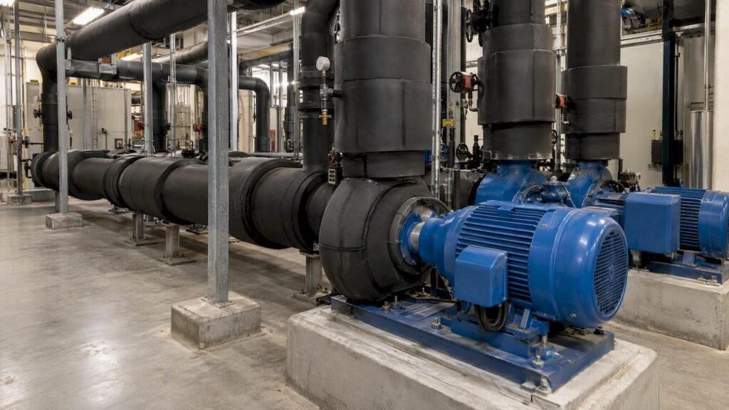
- Maintain a continuous vapor barrier across all insulation, including valve bodies, strainers and pump casings, not just straight pipe runs.
- Specify removable insulation blankets on valves larger than 3 inches to allow maintenance access without destroying the vapor seal.
- Label piping direction and service clearly at regular intervals to speed troubleshooting and reduce commissioning time.
Pro Tip: An uninsulated strainer body is one of the most common sources of condensation drips reported during the first cooling season.
Controls and sequences: BAS points and Guideline 36 logic
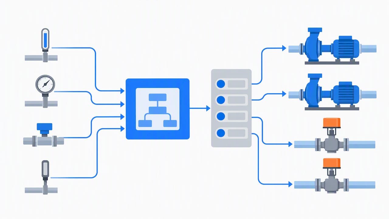
A building automation system (BAS) specification for a chilled water plant needs defined points, not generic “temperature sensor” callouts. Designers should include chilled water supply and return temperature sensors, differential pressure transducers at the end of the distribution loop, and variable-speed pump control variables such as MinCWPspeed, consistent with the sequence variables documented in ASHRAE Guideline 36’s addenda for central plants.
Trim-and-respond reset adjusts chilled water supply temperature and differential pressure setpoint based on actual zone demand, generally outperforming fixed outdoor-air (OA) reset schedules because it responds to what the building is actually doing rather than an assumed correlation with outside temperature. Latent-load coordination still requires a floor on supply temperature reset to protect dehumidification performance.
- Verify each required sensor and control point is installed and reporting to the BAS.
- Confirm trim-and-respond logic adjusts setpoints within the ranges specified in the sequence of operations.
- Run delta-T sweeps at multiple load points to confirm pump speed and chiller staging respond correctly.
- Validate minimum chiller lift and flow constraints against manufacturer data before accepting the sequence as final.
Commissioning, test-and-balance and common operational problems
Plant acceptance testing should verify actual flow rates, achieved delta-T across the full load range, pump curves against design static head, and chiller lift under real operating conditions, not just design-day assumptions.
- Confirm measured delta-T matches design intent at both peak and part-load conditions, since low delta-T is the most common post-occupancy complaint.
- Check for fouling or scaling in heat exchangers and strainers during the first seasonal maintenance cycle.
- Watch for short-cycling on chillers staged too close together in capacity, a frequent cause of premature compressor wear.
- Structure punch-lists by system (plant, distribution, controls) so unresolved items are traceable to a specific subcontractor or sequence step.
A practical checklist for permit-ready chilled water design
Permit-ready chilled water drawings need to satisfy municipal plan reviewers while giving contractors enough detail to bid and build without guesswork. Our mechanical design team prepares packages that cover load calculations, piping and instrumentation diagrams (P&IDs), written sequences of operation, test-and-balance plans, and insulation and labelling schedules as a coordinated set rather than disconnected documents. We also reference our guide to Canadian HVAC design standards and permit timelines when a project faces a tight approval window.
- Load calculations and plant sizing rationale, documented for reviewer and owner reference.
- P&IDs showing every valve, meter and sensor location referenced in the sequence of operation.
- Written sequences of operation aligned with Guideline 36 style logic for BAS programmers.
- Insulation, labelling and test-and-balance schedules bundled with the mechanical drawing set.
What matters most when priorities compete
If a project forces a trade-off, enforce delta-T targets before chasing marginal chiller efficiency gains, since low delta-T quietly inflates pump and pipe costs for the life of the system. Verify control sequences in writing before construction, insulate every valve and strainer body without exception, and commission thoroughly rather than on a compressed schedule. Where redundancy affects occupant safety or critical operations, the added capital for N+1 capacity is worth accepting.
— Sanjay
Support for chilled water system projects can include preparing permit-ready chilled water and broader HVAC design packages covering load calculations, plant sizing, piping layouts, sequences of operation, and construction-ready drawings stamped by a professional engineer.

A typical engagement starts with a load and sizing review, moves through drawing development and BAS sequence writing, and ends with construction support during test-and-balance. Readers managing a mix of trades may also find value in marketing guidance for HVAC contractors as a separate business resource.
- HVAC system design, including chilled water plant and distribution layouts.
- Permit-ready, engineer-stamped drawings built for municipal plan review.
- Coordination support through construction review and commissioning handoff.
Review our HVAC System Design Services page and reach out to discuss a chilled water project scope.
FAQ
What are the disadvantages of a chilled water system?
Chilled water systems require more mechanical room space, piping infrastructure and upfront capital than packaged direct-expansion units, and they depend on properly maintained pumps and water treatment to avoid fouling. Poor delta-T management or undersized distribution piping can also erode the energy advantages the system is designed to deliver.
What type of pipe is best for chilled water systems?
Steel and copper piping are the most common choices for chilled water distribution, selected based on pipe size, pressure class and the project’s design standards. Engineers size and support the piping according to the loads and spacing rules referenced in CSA B52 and ASME B31.5 for the refrigeration-related portions of the system.
How does a chilled water system work?
A chiller cools water, which is then pumped through a piping loop to air handlers and fan coils that transfer the cooling effect to occupied spaces. The warmed return water travels back to the chiller to be cooled again, with pump speed and chiller staging adjusted continuously by the building automation system.
What are common problems with chiller systems?
The most frequent issues are low delta-T syndrome, where return water temperature stays too close to supply temperature and forces excess pump energy, along with fouling in heat exchangers and strainers, and short-cycling when chillers are staged too close together in capacity. Regular test-and-balance checks and seasonal maintenance catch most of these before they affect occupant comfort.
Sources
- Chillers – Natural Resources Canada
- Optimizing chilled water design in high-rises in hot, humid climates | ASHRAE Journal (January 2024)