

Voltage drop calculation is defined as the process of quantifying voltage loss in an electrical circuit caused by conductor resistance over distance. NEC 210.19(A) recommends a maximum 3% drop for branch circuits and no more than 5% combined for feeder plus branch circuits. These thresholds are not arbitrary. Exceeding them causes equipment malfunction, motor overheating, and wasted energy. Circuits exceeding 100 feet require a voltage drop assessment as standard engineering practice. For Ontario contractors and engineers working under the Ontario Electrical Safety Code, these calculations also carry weight during inspections, where voltage drop notes are effectively treated as binding standards when equipment fails to receive adequate voltage.
What is the voltage drop formula and how do you calculate it?

The voltage drop formula for single-phase circuits is VD = (2 × K × I × L) / CM, where each variable carries a specific meaning. Getting these variables right is the difference between a compliant installation and a field failure.
Breaking down the formula variables
- K = resistivity constant of the conductor material. For copper at 75°C, K = 12.9. For aluminum at 75°C, K = 21.2.
- I = actual load current in amperes (not the breaker rating).
- L = one-way circuit length in feet.
- CM = conductor cross-sectional area in circular mils, taken from NEC Chapter 9, Table 8.
- 2 = the multiplier accounting for current traveling both ways in a single-phase circuit.
For three-phase circuits, replace the multiplier of 2 with 1.732, which reflects the geometric relationship between phases. Three-phase systems produce about 13.4% less voltage drop than single-phase for the same conductor size and current. That reduction matters significantly on long commercial runs.
Step-by-step voltage drop example
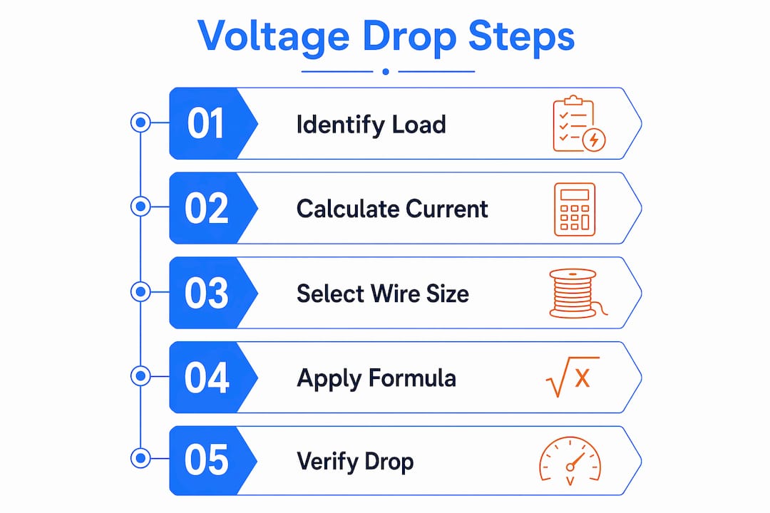
The following worked example uses a 50A EV charger circuit at 150 feet with 8 AWG copper conductor (16,510 CM) on a 240V single-phase circuit.
- Identify variables: K = 12.9, I = 50A, L = 150 ft, CM = 16,510.
- Apply the formula: VD = (2 × 12.9 × 50 × 150) / 16,510.
- Calculate numerator: 2 × 12.9 × 50 × 150 = 193,500.
- Divide: 193,500 / 16,510 = 11.72 volts.
- Calculate percentage: 11.72 / 240 × 100 = 4.88%.
That result exceeds the 3% branch circuit recommendation. Upgrading to 4 AWG copper (41,740 CM) drops the result to 1.93%, well within compliance. The conductor upgrade adds material cost but eliminates the risk of charger malfunction and inspection failure.
| Conductor | CM | Voltage Drop (V) | Drop % |
|---|---|---|---|
| 8 AWG copper | 16,510 | 11.72 | 4.88% |
| 4 AWG copper | 41,740 | 4.63 | 1.93% |
Pro Tip: Always calculate voltage drop percentage against the nominal supply voltage (120V or 240V), not the measured voltage at the panel. Using measured voltage introduces inconsistency across projects.
How do you select wire size and configuration to control voltage drop?
Wire size selection for voltage drop control depends on four factors: conductor material, circuit voltage, one-way run length, and actual load current. Choosing the wrong wire gauge costs money in two directions. Undersizing causes voltage drop failures. Oversizing wastes material and labor.
Copper vs. aluminum conductors
Copper carries more current per circular mil than aluminum, which directly reduces voltage drop for the same wire gauge. Aluminum requires a larger gauge to match copper’s performance. The K-factor difference (12.9 for copper vs. 21.2 for aluminum) means an aluminum conductor produces roughly 64% more voltage drop than the same-sized copper conductor under identical conditions. For long feeder runs in commercial buildings, aluminum is common because the cost savings on large-gauge wire outweigh the performance gap when sized correctly.
- 120V circuits are more sensitive to voltage drop because the same absolute voltage loss represents a larger percentage of the supply voltage. A 3.6V drop on a 120V circuit equals 3%. The same 3.6V drop on a 240V circuit equals only 1.5%.
- 240V circuits allow longer runs before hitting the 3% threshold, which is why EV chargers, HVAC equipment, and dryers use 240V.
- Locating panels and sub-panels closer to loads reduces run length and directly reduces voltage drop without changing wire gauge. This is the most cost-effective design decision available before conductor sizing begins.
Pro Tip: When a calculation shows a conductor needs to be upsized by two or more gauges to meet the voltage drop limit, evaluate whether relocating the sub-panel is more cost-effective. A shorter run often costs less than larger wire across the entire circuit.
Consulting an accurate electrical load list before sizing conductors prevents the most common error in this process: using estimated or breaker-rated current instead of actual expected load current.
What are common mistakes and how to troubleshoot voltage drop issues?
Voltage drop errors fall into two categories: formula errors and design coordination errors. Both lead to field problems, inspection failures, or equipment damage.
Formula errors that inflate or understate results
- Using breaker ampacity instead of actual load current. Breaker ratings do not determine voltage drop. A 20A breaker protecting a 12A load circuit produces a very different voltage drop result than a fully loaded 20A circuit. Using 20A inflates the calculated drop and leads to unnecessary conductor upsizing.
- Omitting the multiplier of 2 in single-phase calculations. The one-way circuit length requires a factor of 2 to account for the return path. Omitting this factor halves the calculated drop and produces a dangerously optimistic result.
- Applying the wrong K-factor. Using the copper K-factor (12.9) on an aluminum conductor (K = 21.2) understates voltage drop by nearly 40%.
Design coordination errors
Treating feeder and branch circuit voltage drop as independent calculations is the most common design error in complex electrical systems. The 5% combined limit requires engineers to budget voltage drop across both segments. If the feeder consumes 3%, the branch circuit budget is only 2%.
Exceeding the 5% combined drop limit is a frequent cause of inspection failures and field complaints in Ontario multi-unit residential and commercial projects.
Motor circuits require additional attention. Motor start-up inrush current significantly exceeds steady-state running current. Sizing a motor circuit for running current alone risks voltage drop during start-up that causes stalls, nuisance tripping, or equipment damage. Engineers must account for transient conditions, not just steady-state operation.
Ambient temperature also affects conductor resistance. Higher temperatures increase resistance and worsen voltage drop. Installations in mechanical rooms, attics, or outdoor conduit runs in Ontario summers require temperature correction factors from NEC Chapter 9.
How do voltage drop considerations differ between residential and commercial installations?
Residential and commercial electrical systems share the same NEC voltage drop recommendations but differ significantly in circuit complexity, load types, and the consequences of non-compliance.
Residential installations
Residential branch circuits in Ontario typically operate at 120V or 240V single-phase. The 3% branch circuit limit applies directly. Common problem circuits include:
- Long kitchen appliance circuits where the panel is located far from the load center.
- Garage or workshop circuits exceeding 50 feet from the panel.
- EV charger circuits, which combine high current (32A to 50A) with long runs to the garage or driveway.
- Outdoor lighting circuits where the panel is centrally located but fixtures are distributed across a large property.
For residential projects, the role of electrical engineers includes verifying that voltage drop calculations are completed for any circuit over 100 feet and documented for permit submission.
Commercial and industrial installations
Commercial systems introduce three-phase distribution, which changes the calculation and the performance outcome. Three-phase systems produce inherently lower voltage drop due to the 1.732 geometric factor, making them the standard choice for long feeder runs and large motor loads. Three-phase systems are ideal for commercial and long-run applications precisely because of this geometric advantage.
| Installation type | Typical supply | Key voltage drop concern |
|---|---|---|
| Residential branch circuit | 120V / 240V single-phase | Long runs to EV chargers, garages, outbuildings |
| Commercial feeder | 208V / 600V three-phase | Feeder and branch coordination across large floor plates |
| Industrial motor circuit | 600V three-phase | Inrush current during motor start-up |
| Medical or sensitive equipment | 120V / 208V | Tighter tolerances; often below 2% |
Sensitive loads such as medical devices, data center equipment, and EV charging infrastructure require tighter voltage tolerances than standard NEC recommendations. These loads often specify less than 2% voltage drop in equipment documentation. Power distribution design for these applications requires detailed calculations and documentation that survives both engineering review and authority-having-jurisdiction inspection.
Coordinating feeder and branch circuit voltage drop across a complex commercial system requires a system-level budget approach. Each design team member must know the feeder drop allocation before sizing branch conductors.
Key Takeaways
Accurate voltage drop calculation requires correct formula inputs, system-level coordination between feeder and branch circuits, and conductor selection based on actual load current rather than breaker ratings.
| Point | Details |
|---|---|
| NEC voltage drop limits | Target 3% for branch circuits and 5% combined for feeder plus branch circuits. |
| Formula accuracy | Use actual load current, the correct K-factor for conductor material, and the appropriate multiplier (2 for single-phase, 1.732 for three-phase). |
| Conductor selection | Upsizing wire gauge or relocating sub-panels are both valid strategies; evaluate cost before defaulting to larger wire. |
| System-level coordination | Budget voltage drop across feeder and branch circuits together; exceeding 5% combined is a common inspection failure point. |
| Sensitive and motor loads | Account for inrush current on motor circuits and apply tighter tolerances for EV chargers, medical equipment, and data loads. |
Why I treat voltage drop budgeting as a system design discipline, not a formula exercise
After working through voltage drop assessments on dozens of Ontario residential and commercial projects, the pattern is consistent. Engineers who treat voltage drop as a formula exercise produce compliant calculations on paper. Engineers who treat it as a system design discipline produce installations that perform correctly in the field.
The most common field problem I encounter is not a formula error. It is a coordination failure. The feeder engineer and the branch circuit designer each hit 3% independently, and nobody catches that the combined drop is 6%. The Ontario Electrical Safety Code inspection process does not always catch this either, because inspectors review individual circuit calculations, not system-level summaries. The burden falls on the design team.
My recommendation: build a voltage drop budget table at the start of every project. Assign a maximum feeder drop and a maximum branch drop before any conductor sizing begins. This forces the coordination conversation early, when changing a panel location costs nothing. Changing it after conduit is installed is expensive.
On conductor upsizing decisions, the cost analysis matters. Going from 8 AWG to 6 AWG on a 30-foot circuit is trivial. Going from 8 AWG to 4 AWG on a 200-foot circuit is a meaningful material cost increase. Always check whether moving the sub-panel 50 feet closer solves the problem at lower cost. In my experience, panel placement decisions made early in design save more money than any conductor upsizing decision made late.
Document every calculation. Ontario permit submissions increasingly require voltage drop calculations for EV charger circuits and large appliance circuits. Having a clean, organized calculation sheet speeds up permit approval and protects the design team if questions arise during inspection.
— Sanjay
Professional voltage drop assessment from Futuregenconsulting
Futuregenconsulting delivers detailed voltage drop calculations and MEP engineering services for residential and commercial projects across Ontario. The firm’s electrical engineering team applies over 30 years of experience to conductor sizing, feeder coordination, and code compliance documentation for projects ranging from single-family home renovations to large commercial developments.

Every engagement includes calculation documentation formatted for Ontario permit submission and Electrical Safety Authority review. Whether the project involves EV charger circuits, three-phase commercial feeders, or sensitive medical equipment loads, Futuregenconsulting tailors the electrical design to the specific performance requirements of each installation. Contact Futuregenconsulting to schedule a consultation on your next project.
FAQ
What is the standard voltage drop limit for branch circuits?
NEC 210.19(A) recommends a maximum 3% voltage drop for branch circuits and 5% combined for feeder plus branch circuits. These are performance targets, not mandatory code requirements, but Ontario inspectors treat them as binding when equipment fails to operate correctly.
How do I calculate voltage drop for a single-phase circuit?
Use the formula VD = (2 × K × I × L) / CM, where K = 12.9 for copper at 75°C, I is the actual load current in amperes, L is the one-way circuit length in feet, and CM is the conductor area in circular mils from NEC Chapter 9, Table 8.
Does wire gauge affect voltage drop?
Wire gauge directly determines the circular mil area (CM) in the voltage drop formula. A larger gauge (lower AWG number) increases CM and reduces voltage drop proportionally. Doubling the CM value approximately halves the voltage drop for the same circuit conditions.
Why do three-phase systems have lower voltage drop?
Three-phase circuits use a multiplier of 1.732 instead of 2 in the voltage drop formula, producing approximately 13.4% less voltage drop than single-phase for identical conductor size and current. This geometric advantage makes three-phase distribution the standard for commercial and industrial long-run applications.
When does voltage drop become an inspection issue in Ontario?
Voltage drop becomes enforceable when equipment fails to receive adequate voltage as required by its listing or when local amendments to the Ontario Electrical Safety Code specify minimum voltage performance. Inspectors increasingly require documented calculations for EV charger circuits and large appliance loads during permit review.