
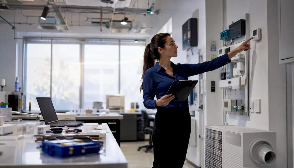
Demand controlled ventilation (DCV) is an automatic ventilation control strategy that resets outdoor airflow to match actual building occupancy in real time, reducing the energy cost of conditioning unnecessary outdoor air while maintaining compliant indoor air quality. For Canadian commercial projects, DCV is most cost-effective in spaces with high per-person ventilation requirements and variable occupancy: theaters, lecture halls, classrooms, conference rooms, and retail floors. It is unlikely to pay back in spaces with constant high-density occupancy, 100% outdoor air systems sized for free cooling, or air-handling units (AHUs) with insufficient fan turndown capability.
- When DCV is strongly recommended: High-density, variable-occupancy spaces where the breathing-zone outdoor air rate (Vbz) per ASHRAE 62.1 is dominated by the people component rather than the floor-area component.
- When DCV is unlikely to pay back: Constant-occupancy spaces, 100% OA systems where economizer free cooling drives the design, or systems where minimum AHU fan turndown prevents meaningful airflow reduction.
- Code drivers: ASHRAE 90.1 mandates DCV for certain high-occupancy spaces; ASHRAE 62.1 defines the ventilation rate procedure (VRP) that DCV must satisfy operationally; the National Energy Code for Buildings (NECB) and provincial energy codes in Canada reference or adopt 90.1 thresholds.
Primary sensor types used in practice are CO2 sensors (most common), occupancy counters, and VOC or humidity sensors as supplementary inputs. ASHRAE Standard 62.1 is the governing operational standard; ASHRAE 90.1 Section 6.4.3.8 is the energy-code trigger for mandatory DCV in qualifying spaces.
Table of Contents
- What demand controlled ventilation is and how it differs from constant-volume systems
- Energy savings versus IAQ trade-offs: quantified benefits and the main risks
- Sensor types, placement, accuracy limits, and calibration schedules
- Applicable codes and standards for DCV on Canadian projects
- Which building types and spaces are the best and worst candidates for DCV
- Recommended control sequences, setpoints, and BAS integration
- How to specify, design, commission, and hand over a DCV system
- Known failure modes in DCV systems and how to mitigate them
- Typical installed costs, payback ranges, and Canadian climate considerations
- How Futuregenconsulting approaches DCV design and commissioning on Canadian projects
- Key Takeaways
- The direction DCV technology and practice are heading
- Futuregenconsulting’s DCV engineering services for Ontario projects
- Useful sources and further reading
What demand controlled ventilation is and how it differs from constant-volume systems
In engineering terms, DCV resets the breathing-zone outdoor air quantity (Vbz) continuously or in steps based on current population, rather than supplying the design-maximum outdoor airflow at all times. Under the ASHRAE 62.1 Ventilation Rate Procedure, Vbz is the sum of a people-dependent component (Rp × Pz) and an area-dependent component (Ra × Az). DCV exploits the fact that Pz, the zone population, is rarely at design maximum, so the people component of Vbz can be reduced proportionally when occupancy is low.
This distinguishes DCV from two related but distinct strategies. A constant outdoor-air system supplies a fixed OA quantity sized for design occupancy regardless of actual population, which is safe but wastes conditioning energy during partial occupancy. An economizer control strategy modulates OA to exploit low outdoor temperatures or enthalpies for free cooling, with the control variable being outdoor temperature or enthalpy rather than occupancy. DCV and economizer logic can coexist in the same AHU, but they pursue different objectives and must be coordinated in the sequence of operations to avoid conflicts, particularly when the economizer drives OA above the DCV setpoint.
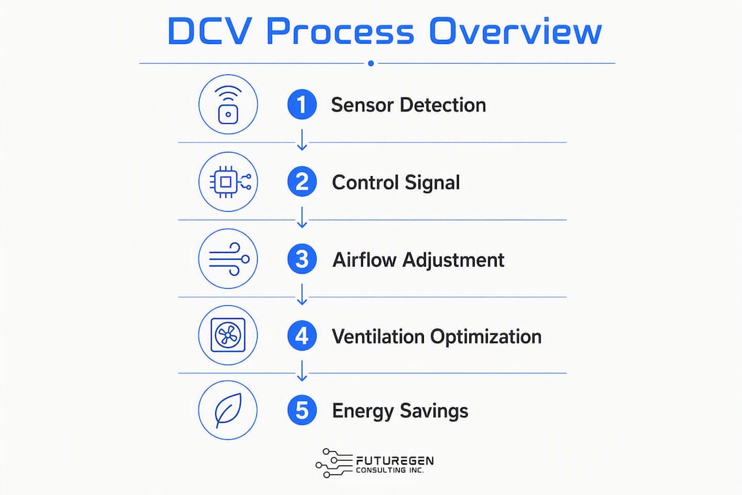
The physical control path is straightforward: a CO2 sensor or occupancy counter sends a signal to the direct digital control (DDC) system, which adjusts the OA damper position, variable air volume (VAV) box minimum setpoint, or dedicated outdoor air system (DOAS) supply fan speed to deliver the calculated Vbz. In a single-zone recirculating AHU, the OA damper is the primary actuator. In a VAV system, the sequence typically resets the minimum OA setpoint at the AHU based on a critical-zone calculation. In a DOAS topology, the supply fan speed or a modulating valve controls OA delivery directly to each zone.
Energy savings versus IAQ trade-offs: quantified benefits and the main risks
Ventilation air heating represents a significant portion of a commercial building’s total heating energy, making it one of the largest controllable loads in Canadian climates where heating seasons are long and outdoor air temperatures are extreme. DCV reduces that load in direct proportion to the reduction in OA volume during partial occupancy. The savings are highest in heating-dominated climates like those in Ontario, Alberta, and Manitoba, where the enthalpy difference between outdoor and indoor air is large for most of the operating year.
Statistic: Ventilation air heating can represent up to 30% of total commercial building heating energy, making DCV one of the highest-leverage energy measures available in Canadian climates.
The IAQ trade-off centers on CO2 as a proxy for occupancy. CO2 concentration in a space reflects the balance between occupant metabolic output and outdoor air dilution, but it does not directly measure ventilation rate. Non-human CO2 sources (combustion equipment, dry ice, some lab processes), sensor lag during rapid occupancy changes, and infiltration or window-opening contributions can all cause the CO2 signal to misrepresent actual ventilation adequacy. CO2 alone cannot reliably quantify population without airflow measurement or occupancy counts, which is why hybrid methods combining CO2 with measured OA airflow are increasingly preferred.
Spaces where DCV investment is most justified:
- Theaters and auditoriums: high per-person OA rates, occupancy varies sharply between performances and off-hours.
- Classrooms and lecture halls: occupancy follows predictable schedules but drops to near-zero outside class hours.
- Retail floors: occupancy varies by time of day and season, with significant off-hours periods.
- Conference rooms: among the highest per-person OA rates in ASHRAE 62.1 Table 6-1, with highly variable occupancy.
Pro Tip: In conference rooms, the per-person OA rate under ASHRAE 62.1 is among the highest of any space type. A single 20-person conference room that is occupied less than 40% of operating hours can justify sensor and control costs within two to three heating seasons in a Canadian climate.
Integrating DCV with supervisory control strategies such as temperature setback and supply-air reset consistently yields better energy outcomes than DCV operating in isolation, because the reduced OA load interacts with reduced heating and cooling setpoints during low-occupancy periods.
Sensor types, placement, accuracy limits, and calibration schedules
Comparing sensor approaches
| Sensor Type | What It Measures | Suitable Topology | Key Error Modes |
|---|---|---|---|
| CO2 (NDIR) | Metabolic CO2 as occupancy proxy | Single-zone recirc, VAV, DOAS | Sensor drift, non-human sources, lag during rapid occupancy change |
| Occupancy counter (PIR / video / BLE) | Direct headcount or presence | Single-zone, DOAS, high-accuracy VAV | Counting errors at entrances, privacy constraints, calibration complexity |
| OA airflow meter (pitot array, thermal) | Actual OA volume at AHU or zone | AHU-level DCV, DOAS | Duct installation requirements, low-flow accuracy limits |
| VOC / humidity sensor | Pollutant load or moisture as supplementary signal | Supplementary to CO2 or occupancy | Not a standalone occupancy proxy; requires calibration to specific contaminants |
CO2 is widely deployed as a proxy for occupancy, and guidance recommends combining CO2 with measured OA airflow or occupancy detection where feasible. Directly measuring or limiting outdoor airflow at the AHU or DOAS and combining that with CO2 measurement improves DCV reliability and compliance with ASHRAE 62.1. This hybrid approach reduces the compliance risk inherent in CO2-only systems, particularly in spaces where non-human CO2 sources are plausible.
Sensor placement rules
- Mount CO2 sensors in the return air stream or in the occupied zone at breathing height (1.1–1.7 m above floor), not in supply air or near diffusers.
- In multi-zone VAV systems, zone-level CO2 sensors are required for zone-by-zone DCV; a single return-duct sensor is acceptable only for single-zone systems.
- Outdoor CO2 measurement is required for algorithms that calculate the differential between indoor and outdoor CO2 to estimate ventilation effectiveness; a fixed outdoor reference of 400–420 ppm is a common simplification but introduces error during wildfire smoke events or urban conditions.
- Keep sensors away from doors, windows, and operable vents where infiltration dilutes the CO2 reading and produces false low readings.
Calibration schedule
A study showed 19% of installed CO2 sensors required calibration over a 15-month period, confirming that sensor drift is a real operational risk, not a theoretical one. ASHRAE Guideline 36-2024 permits automatic background calibration for CO2 space sensors in some systems, which reduces field labor, but background calibration has performance limits during winter purge restrictions when spaces may not reach outdoor CO2 levels.
Recommended calibration practice:
- Annual field calibration using a certified reference gas for all CO2 sensors without auto-background capability.
- Auto-background calibration where Guideline 36-2024 permits it, with manual verification at least every two years and after any sensor replacement.
- Post-event verification after building shutdowns longer than two weeks, wildfire smoke events, or any HVAC control system changes.
Pro Tip: Specify calibration requirements in the service contract at the time of commissioning, not as a retrofit. Sensor drift accumulates silently; by the time an operator notices IAQ complaints, the DCV system may have been under-ventilating for months. For detailed Guideline 36 calibration requirements, see Futuregenconsulting’s ASHRAE Guideline 36 practical guide.
Applicable codes and standards for DCV on Canadian projects
Canadian DCV projects sit at the intersection of three regulatory layers: ASHRAE operational standards, energy codes, and the National Building Code of Canada (NBC) / provincial amendments.
ASHRAE Standard 62.1 defines the Ventilation Rate Procedure and the operational requirement to provide breathing-zone outdoor air matched to actual population. The DCV clause in 62.1 permits reducing OA below design maximum when occupancy is below design, provided the control system can verify population and the minimum OA floor-area component (Ra × Az) is always maintained. The ANSI/ASHRAE Addendum ab to ASHRAE Standard 62.1-2022 addresses CO2-based DCV control directly, clarifying the conditions under which CO2 setpoints satisfy the VRP.
ASHRAE Standard 90.1 is an energy code standard. Section 6.4.3.8 mandates DCV for spaces with design occupancy above 25 people per 1,000 ft² (approximately 269 people per 1,000 m²) and design OA above 3,000 CFM. These thresholds make DCV mandatory for classrooms, conference rooms, auditoriums, and similar high-density spaces in jurisdictions that adopt 90.1.
The National Energy Code for Buildings (NECB) and provincial energy codes in Canada reference or adopt 90.1 thresholds with provincial amendments. Ontario’s Building Code and the Ontario Society of Professional Engineers’ guidance align with NECB requirements. The National Building Code of Canada Part 5 governs HVAC system design and construction requirements, within which DCV sequences must be documented and compliant.
Statistic: ASHRAE 90.1 Section 6.4.3.8 triggers mandatory DCV for spaces with high design occupancy density and outdoor air volume thresholds, covering most classrooms, auditoriums, and conference rooms in Canadian commercial buildings.
ASHRAE Guideline 36-2024 provides high-performance sequences of operation including DCV integration, sensor auto-calibration permissions, and supervisory override logic. While not a code document, Guideline 36 is increasingly referenced in project specifications and by authorities having jurisdiction (AHJs) as best practice.
Compliance checklist for designers proposing DCV:
- Confirm space type and design occupancy density against 90.1 Section 6.4.3.8 thresholds.
- Verify AHU or VAV box minimum turndown capability (typically 30–50% of design airflow) to confirm the system can physically reduce OA.
- Confirm OA measurement instrumentation is specified at the AHU or zone level to verify minimum OA floor-area component is maintained.
- Document the DCV control sequence in the mechanical drawings and sequence of operations narrative.
- Identify any non-human CO2 sources in or adjacent to the served space and address them in sensor placement or control logic.
- Coordinate with the authority having jurisdiction on whether NECB or provincial energy code amendments modify 90.1 thresholds for the specific project location.
Which building types and spaces are the best and worst candidates for DCV
High-ROI applications
Theaters and auditoriums represent the clearest DCV case: per-person OA rates are high under ASHRAE 62.1 Table 6-1, and occupancy swings from near-zero during rehearsals or off-hours to full capacity during performances. The energy cost of supplying design-maximum OA to an empty 500-seat auditorium is substantial in a Canadian heating climate.
Classrooms and lecture halls follow the same logic. Occupancy is predictable by schedule, but the hours between classes, evenings, and weekends represent significant unoccupied periods during which a constant-OA system wastes conditioning energy. Conference rooms have among the highest per-person OA rates in 62.1 and are frequently occupied at a fraction of design capacity.
Retail floors benefit from DCV because occupancy varies significantly by time of day and season, and the floor areas are large enough that the area component of Vbz alone does not justify full design OA during off-peak hours.
Poor-fit situations
- 100% OA systems sized for free cooling: When the economizer drives OA to 100% for free cooling, DCV cannot reduce OA below that level without defeating the economizer strategy. The two strategies conflict unless the sequence explicitly coordinates them.
- Constant high-density occupancy: A data center support space or a manufacturing floor with continuous full staffing provides no occupancy variability for DCV to exploit.
- AHU or VAV turndown limits: If the minimum fan speed or VAV box minimum stop prevents meaningful OA reduction, the control system cannot execute the DCV sequence. Verify turndown before specifying DCV.
- Spaces with significant non-human CO2 sources: Laboratories, commercial kitchens, and spaces with combustion equipment require specialized ventilation design that goes beyond CO2-based DCV.
Quick decision checklist:
- Is design occupancy density above 25 people per 1,000 ft²? If yes, 90.1 may mandate DCV.
- Does occupancy vary by more than 50% from design maximum during normal operating hours? If yes, DCV has energy savings potential.
- Can the AHU or VAV system turn down to at least 50% of design airflow? If no, DCV cannot be executed.
- Are non-human CO2 sources present? If yes, plan for hybrid sensing or OA flow measurement.
- Is the system a 100% OA economizer-dominated design? If yes, evaluate conflict with economizer before specifying DCV.
Recommended control sequences, setpoints, and BAS integration
Three canonical DCV control sequences
1. Fixed CO2 setpoint with airflow limits
The simplest and most common approach. The DDC system modulates OA damper or VAV minimum setpoint to maintain zone CO2 at or below a fixed setpoint, typically 1,000–1,100 ppm (approximately 600–700 ppm above outdoor ambient). A hard minimum OA floor is enforced at all times equal to Ra × Az to satisfy the area component of Vbz.
Steps:
- Read zone CO2 sensor (ppm).
- If CO2 < setpoint (e.g., 1,000 ppm), reduce OA to minimum floor (Ra × Az).
- If CO2 ≥ setpoint, modulate OA upward in proportion to the error signal until CO2 returns below setpoint.
- Enforce hard minimum OA at all times; enforce hard maximum OA at design Vbz.
- Log CO2 and OA flow for M&V.
2. Measured OA airflow plus CO2 population estimation
Combining OA airflow measurement at the AHU or ventilation zone with CO2 measurement improves compliance certainty under ASHRAE 62.1. The OA flow meter provides a direct check that the minimum OA floor is being delivered; the CO2 signal drives the population-proportional reset above that floor.
Steps:
- Measure actual OA flow at AHU (CFM or L/s) via pitot array or thermal flow meter.
- Enforce minimum OA = Ra × Az regardless of CO2 reading.
- Use CO2 differential (indoor minus outdoor) to estimate current population Pz.
- Calculate required Vbz = (Rp × estimated Pz) + (Ra × Az).
- Modulate OA to deliver calculated Vbz, subject to system turndown limits.
- Alarm if measured OA falls below minimum floor for more than a configurable time period.
3. Direct occupancy-count reset
Where occupancy counters (PIR arrays, video analytics, or badge/access data) provide a reliable headcount, the DDC system calculates Vbz directly from the count without relying on CO2 as a proxy. This eliminates CO2 lag and non-human source errors but requires reliable counting infrastructure and privacy compliance.
Steps:
- Receive occupancy count from counter system via BAS protocol (BACnet, Modbus).
- Calculate Vbz = (Rp × count) + (Ra × Az).
- Modulate OA to deliver Vbz, subject to minimum floor and maximum design limits.
- Maintain CO2 monitoring as an independent IAQ alarm, not as the primary control variable.
BAS integration checklist
- Supervisory overrides: Program occupied, unoccupied, and warm-up modes with explicit OA setpoints for each mode; DCV logic must be disabled or held at minimum during warm-up to prevent cold-air complaints.
- Economizer coordination: When outdoor conditions trigger economizer mode, the DCV minimum OA setpoint becomes the lower bound; the economizer drives OA above that bound as needed for free cooling.
- Alarms: Configure alarms for CO2 above 1,100 ppm (IAQ alert), OA flow below minimum floor (compliance alert), and sensor out-of-range (maintenance alert).
- Data logging: Log CO2 (ppm), OA flow (CFM or L/s), occupancy count (if available), and OA damper position at minimum 15-minute intervals for M&V.
- M&V hooks: Export logged data to the building energy management system or a third-party analytics platform for baseline and post-commissioning comparison.
Pro Tip: Treat DCV as a sequence-of-operation problem, not a sensor installation. Supervisory integration with temperature setback and supply-air reset consistently increases savings and system robustness beyond what CO2 control alone achieves. Specify the full integrated sequence in the mechanical drawings, not just the sensor type.
How to specify, design, commission, and hand over a DCV system
Specification language guidance
The mechanical specification should include, at minimum:
- Control intent statement: — “The DCV system shall modulate outdoor air delivery to each zone to maintain the breathing-zone outdoor air rate (Vbz) per ASHRAE 62.1 VRP at current occupancy, subject to a minimum OA floor equal to Ra × Az at all times.”
Commissioning test list
- OA flow verification: Measure actual OA flow at design occupancy setpoint and at minimum floor setpoint; confirm against design values within ±10%.
- CO2 response lag test: Introduce a known CO2 load (occupants or calibrated source) and verify the control system responds within the specified lag time (typically 15–30 minutes for room-level sensors).
- Sensor calibration verification: Verify all CO2 sensors against a certified reference gas at commissioning; document results in the commissioning report.
- Minimum OA floor verification: Confirm the system cannot reduce OA below Ra × Az under any control condition, including unoccupied mode.
- Alarm function test: Verify CO2 high alarm, OA low alarm, and sensor fault alarm all trigger correctly at the BAS.
Handover checklist for operations staff
- Provide as-built sequence of operations document with annotated control diagrams.
- Demonstrate DCV mode, override mode, and alarm response at the BAS operator workstation.
- Deliver sensor calibration certificates and schedule the first annual recalibration date in the service contract.
- Provide a one-page operator reference card showing CO2 setpoints, alarm thresholds, and override procedures.
Pro Tip: The most cost-effective commissioning investment is a clear, operator-readable sequence-of-operations document. A frequent field failure is the handoff between designer and operator: when the DCV sequence and OA damper scheduling are not clearly documented and demonstrated during commissioning, operators override DCV logic within the first year, eliminating all projected savings.
M&V plan template
| Data Point | Logging Interval | Acceptance Threshold | Reporting Cadence |
|---|---|---|---|
| Zone CO2 (ppm) | 15 minutes | < 1,100 ppm during occupied hours | Monthly summary, annual report |
| OA flow (CFM or L/s) | 15 minutes | ≥ Ra × Az at all times | Monthly summary, annual report |
| Occupancy count (if metered) | 15 minutes | ±10% of manual count verification | Quarterly verification |
| Fan energy (kWh) | Hourly | Compared to pre-DCV baseline | Annual report |
| Heating energy (kWh or GJ) | Hourly | Compared to pre-DCV baseline | Annual report |
Known failure modes in DCV systems and how to mitigate them
| Failure Mode | Mechanism | Consequence | Mitigation |
|---|---|---|---|
| CO2 sensor drift | Gradual NDIR calibration shift over months | Under- or over-ventilation without alarm | Annual calibration; auto-background calibration per Guideline 36-2024 where applicable |
| Non-human CO2 sources | Combustion, dry ice, lab processes elevate CO2 | False high CO2 triggers excess OA (over-ventilation) | Survey space for non-human sources; use OA flow measurement as primary control |
| Sensor placement error | Sensor near supply diffuser or window | Diluted CO2 reading causes under-ventilation | Follow ASHRAE 62.1 Addendum ab placement guidance; return-air or breathing-zone mounting |
| AHU fan turndown limit | Minimum fan speed prevents OA reduction | DCV cannot execute; no energy savings | Verify turndown at design stage; specify variable-frequency drives with adequate turndown range |
| Occupancy sensor mismatch | Lighting and HVAC occupancy sensors have mismatched timeouts | Ventilation lag or failure to initiate required OA | Coordinate electrical and mechanical trades; align occupancy sensor timeouts across lighting and HVAC control systems |
| Economizer conflict | Economizer drives OA above DCV setpoint without coordination | DCV logic fights economizer; control instability | Sequence economizer as upper-bound override; DCV sets minimum, economizer sets maximum |
| Rapid occupancy change lag | CO2 takes 15–30 minutes to reflect sudden occupancy increase | Transient under-ventilation at event start | Use occupancy counters as lead signal; set CO2 alarm at 1,000 ppm to trigger early response |
Mitigation checklist:
- Specify redundant CO2 sensors in high-consequence spaces (auditoriums, healthcare waiting areas).
- Require OA flow measurement as a hard minimum floor check independent of CO2 signal.
- Include sensor drift verification in the annual service contract with documented pass/fail criteria.
- Coordinate occupancy sensor timeouts between electrical and mechanical specifications at design stage.
- Test economizer-DCV interaction explicitly during commissioning functional testing.
Pro Tip: Commissioning documentation is the most cost-effective mitigation for the design-to-operations handoff failure. A well-documented sequence of operations, with annotated control diagrams and operator training, costs a fraction of the energy waste and IAQ liability that follows when operators disable DCV logic because they do not understand it.
Typical installed costs, payback ranges, and Canadian climate considerations
Cost breakdown
| Cost Element | Typical Range (CAD) | Notes |
|---|---|---|
| CO2 sensors (per zone) | — | NDIR type with BACnet output; installed cost |
| OA flow meter (per AHU) | — | Pitot array or thermal; includes duct installation |
| Control I/O and BAS integration (per AHU) | $2,000 | DDC point additions, programming, and commissioning |
| Commissioning and functional testing | $3,000–$4,000 per system | Includes sensor calibration verification and M&V setup |
| Annual service (calibration, sensor check) | $500 per year | Per service contract; varies by sensor count |
A typical 10-zone office floor with one AHU and 10 CO2 sensors would carry an installed cost in the range of $15,000–$30,000 CAD, depending on BAS complexity and whether OA flow metering is included.
Statistic: Ventilation air heating can account for up to 30% of a commercial building’s total heating energy. In a heating-dominated Canadian climate, this makes DCV one of the highest-leverage energy measures available for variable-occupancy spaces.
Sample payback calculation (conservative assumptions)
Building: 2,000 m² office floor, Ontario climate, natural gas heating.
Assumption: DCV reduces average OA by 35% during occupied hours (conservative for a mixed-use floor with conference rooms and open office).
Annual ventilation heating energy without DCV: Estimated from load calculations; not fabricated here as a specific figure.
Simple payback: Varies materially with occupancy profile, minimum OA setpoint, and fan turndown ratio.
The key modeling variables that change payback most significantly are:
- Minimum OA floor: A higher Ra × Az floor (large floor area, low occupancy density) limits how much OA DCV can reduce, compressing savings.
- Fan turndown ratio: A system that can turn down to 30% of design airflow saves more fan energy than one limited to 60%.
- Occupancy schedule: A space occupied 40 hours per week at variable density saves more than one occupied 60 hours per week at near-constant density.
- Climate zone: Modeling guidance requires verification of minimum fan turndown, occupancy schedules, and density assumptions to avoid overestimating savings. Ontario and Alberta projects in heating-dominated climates typically show stronger payback than milder Canadian climates because the enthalpy difference between outdoor and indoor air is larger for more months of the year.
For HVAC load calculation and energy modeling, the ventilation heating fraction must be calculated from the actual design rather than assumed from benchmarks, as building envelope performance and internal gains affect the share materially.
How Futuregenconsulting approaches DCV design and commissioning on Canadian projects
Futuregenconsulting’s HVAC system design practice covers the full DCV project scope: site survey and space classification, sensor selection and placement design, BAS sequence development, permit-ready drawing packages, commissioning test plans, and M&V reporting. The firm’s Ontario-based team applies ASHRAE 62.1, 90.1, and NECB requirements directly to project specifications, with provincial code amendments incorporated as standard practice.
A representative project scope for a DCV engagement includes:
- Control sequence development: — Full sequence of operations document per ASHRAE Guideline 36-2024 patterns, including economizer coordination, supervisory overrides, alarm setpoints, and M&V data logging requirements.
Building managers and developers seeking a technical review of a proposed DCV scope or a project estimate can engage Futuregenconsulting through the MEP engineering services page.
Key Takeaways
Demand controlled ventilation delivers its strongest ROI in high-density, variable-occupancy Canadian spaces where ventilation heating load is high, provided the AHU has adequate fan turndown and the control sequence is fully integrated with BAS supervisory logic.
| Point | Details |
|---|---|
| Where DCV pays | Theaters, classrooms, conference rooms, and retail floors with variable occupancy in heating-dominated Canadian climates. |
| Must-check design constraints | Verify AHU fan turndown to at least 50% of design airflow and confirm OA flow measurement capability before specifying DCV. |
| CO2 is a proxy, not a measurement | Combine CO2 sensing with OA airflow measurement to reduce compliance risk under ASHRAE 62.1 and 90.1. |
| Commissioning is non-negotiable | Document the full sequence of operations and verify sensor calibration at handover; operator overrides are the leading cause of DCV failure in the field. |
| Futuregenconsulting | Provides full-scope DCV design, commissioning, and M&V services for Ontario commercial projects, with permit-ready drawings and code-compliant sequences. |
The direction DCV technology and practice are heading
The most significant shift in DCV practice over the next five years will not be sensor technology. It will be the integration of real-time occupancy analytics with BAS supervisory control, moving the industry away from CO2 as the primary control variable toward direct population measurement. CO2-based DCV has served the industry well as a low-cost proxy, but its limitations are well-documented: lag, non-human sources, and the inability to distinguish between a room with 10 people and good infiltration from a room with 20 people and poor infiltration. As occupancy counting technology (video analytics, BLE beacons, access control integration) becomes more affordable and privacy-compliant, the case for CO2 as the sole control variable weakens.
The second shift is regulatory. ASHRAE and Canadian energy code authors have grown more cautious about CO2-only approaches, and the trend in addenda to 62.1 and in Guideline 36-2024 is toward requiring or strongly recommending OA flow measurement as a verification layer. Projects that specify CO2-only DCV without an OA flow measurement floor are increasingly exposed to compliance questions during commissioning and re-commissioning.
Emerging trends worth tracking:
- Real-time OA metering as standard practice: OA flow meters at AHUs and DOAS units are moving from optional to expected in high-performance specifications.
- Improved sensor auto-calibration: Guideline 36-2024’s auto-background calibration provisions reduce field labor, but winter purge limitations in Canadian climates require manual verification protocols.
- DOAS plus DCV adoption: Dedicated outdoor air systems with zone-level CO2 or occupancy control are gaining ground in new construction because they decouple ventilation from thermal conditioning, making DCV sequences cleaner and more reliable.
- BAS analytics and commissioning automation: Cloud-connected BAS platforms that flag CO2 exceedances, sensor drift, and OA flow deviations in real time are reducing the gap between design intent and operational reality.
- Regulatory pressure on minimum OA floors: Expect future NECB and provincial energy code amendments to tighten minimum OA floor requirements, which will affect DCV savings calculations and payback projections.
The practitioners who will get the most out of DCV in the next decade are those who treat it as an integrated control strategy, not a sensor product. The sensor is the least important part of the system.
Futuregenconsulting’s DCV engineering services for Ontario projects
For building professionals who need more than a general framework, Futuregenconsulting delivers permit-ready DCV engineering packages for Ontario commercial projects, backed by over 30 years of MEP design experience and direct application of ASHRAE 62.1, 90.1, NECB, and Ontario Building Code requirements.

The firm’s DCV engagements are scoped to what the project actually needs: a site survey and code-compliance review for projects in early design, a full design and drawing package for permit submission, or a commissioning and M&V scope for projects where the system is already installed but performance is unverified. Every deliverable is stamped by a licensed professional engineer and written to be executable by the contractor and understandable by the building operator.
Typical DCV engagement deliverables:
- Space classification and occupancy density analysis per ASHRAE 62.1 VRP
- Sensor selection, placement drawings, and OA flow meter specifications
- Full sequence of operations per Guideline 36-2024 patterns, including economizer coordination and BAS alarm setpoints
- Permit-ready mechanical drawings and control diagrams
- Commissioning test plan with functional test procedures and acceptance criteria
- Operator training documentation and handover package
- M&V reporting at 90 days and 12 months post-commissioning
To request a technical review or project estimate, contact Futuregenconsulting through the HVAC system design services page or visit the MEP engineering services overview to understand the full scope of design and compliance services available for Ontario projects.
Useful sources and further reading
The following references provide the authoritative technical and regulatory basis for DCV design and compliance work on Canadian projects. Read them in the order listed: standards first, then technical guidance, then improvement papers.
Essential standards (read first):
- ANSI/ASHRAE Addendum ab to ASHRAE Standard 62.1-2022 — Defines CO2-based DCV control conditions under the Ventilation Rate Procedure; required reading for any CO2 DCV specification.
- National Building Code of Canada — Part 5: Heating, Ventilating and Air-Conditioning — Governing code for HVAC system design and construction in Canada; DCV sequences must comply with Part 5 requirements.
Technical guidance (read second):
- HVAC Guide to Demand Control Ventilation (CED Engineering) — Practical overview of DCV strategies, energy savings drivers, and application guidance; useful for design teams new to DCV.
- Demand Control Ventilation — Alberta TDR Guidance Document — Canada-specific technical guidance covering sensor calibration, Guideline 36-2024 auto-calibration provisions, and modeling verification requirements.
- Government of Canada Technical Fact Sheet: HVAC Controls and Energy Conservation — DDC adoption guidance and recommended integrated control strategies including DCV, supply-air reset, and optimal start.
- NRC Research: DCV Integration with Supervisory Control — NRC-supported research on integrating DCV with supervisory strategies for improved energy performance.
Improvement papers and reliability methods (read third):
- CO2 Monitoring for Demand Controlled Ventilation (Lawrence Berkeley National Laboratory) — Documents CO2 proxy limitations and recommends hybrid methods combining CO2 with OA airflow measurement.
- Reliable DCV Methods: Meeting Ventilation Requirements While Minimizing Energy — Identifies CO2-only DCV uncertainties and presents improved methods including direct OA flow measurement.
- Improve Traditional CO2-DCV with Outdoor Airflow Measurement — Describes two hybrid DCV methods that combine CO2 sensing with OA flow metering for improved ASHRAE 62.1 compliance certainty.