
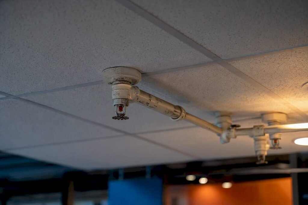
Sprinkler design density is the minimum water discharge rate, expressed in gallons per minute per square foot (gpm/ft²) or liters per minute per square meter (L/min/m²), that a fire sprinkler system must deliver over a defined design area to control a fire of a given hazard classification. The required value is not calculated from scratch. It is selected from the single-point density table in NFPA 13, based on the occupancy hazard classification assigned to the space.
Typical single-point values correspond to Light Hazard, Ordinary Hazard Group 1 and 2, and Extra Hazard Group 1 and 2 categories, with densities increasing by hazard class but without specifying exact numerical ranges.
The single biggest shift in modern sprinkler hydraulics is the elimination of the flexible density/area curves that once let designers trade density against area along a sliding scale. Current editions of NFPA 13 lock designers into one fixed density paired with one fixed area for each hazard class, which removes a whole category of judgment calls that used to generate plan review disputes.
Key Takeaways
Sprinkler design density works only when the correct NFPA 13 single-point value is matched to the correct hazard classification and design area, then verified through a full progressive hydraulic calculation.
| Point | Details |
|---|---|
| Density comes from a table | NFPA 13’s single-point table sets density by hazard class; it is looked up, not calculated. |
| Classification drives everything | Light, Ordinary Group 1/2, and Extra Hazard Group 1/2 each lock in a fixed density and area. |
| Design area has conditions | The 3,000 ft² area applies only next to unsprinklered combustible concealed spaces, not by default. |
| Calculations run backward | Start at the most remote head and accumulate flow and friction loss toward the riser. |
| Professional support closes gaps | FutureGen Consulting provides stamped hydraulic calculations and plan review support for Ontario and Alberta projects. |
Standards and Guidance Worth Bookmarking
- NFPA 13 standard development
- NFPA’s density/area method explainer
- UpCodes hydraulic calculation methods summary
Table of Contents
- What Is Sprinkler Design Density and How Is It Measured?
- Where Do Design Density Values Come From?
- How Do You Choose the Sprinkler Design Area?
- How Do Engineers Calculate Sprinkler Hydraulic Demand?
- Metric Worked Example: From Density to Riser Demand
- What Are the Most Common Sprinkler Design Errors?
- Quick Reference: Conversions and Submission Checklist
- Sources
What Is Sprinkler Design Density and How Is It Measured?
Design density is the minimum discharge rate assumed to occur simultaneously from every sprinkler head operating within the design area, not just the single most remote head. It is a system-level performance criterion, not a per-head spec sheet number. The K-factor and orifice size of an individual sprinkler determine how much flow that head produces at a given pressure, but design density tells you what the whole group of heads in the design area must deliver together, per square foot of floor coverage.
Two unit systems show up in practice. American plans use gpm/ft², while metric-based projects, including many submitted in Canada, use L/min/m². The rough conversion: 1 gpm/ft² equals approximately 40.7 L/min/m², and 1 ft² equals 0.0929 m².
These figures come from the published single-point table, not from an independent calculation you run yourself. Every new design should reference the current table for the exact value, since minor revisions between editions do occur.
Where Do Design Density Values Come From?
NFPA 13 is the primary reference for design density, and the specific single-point density table (commonly cited as Table 19.2.3.1.1 in recent editions) is where the number actually lives. You do not derive density from first principles. You classify the occupancy, look up the row, and read the value across.
Occupancy hazard classification drives the entire selection process:
- Light Hazard: offices, schools, churches, and similar occupancies with low fuel loads and slow anticipated fire growth.
- Ordinary Hazard Group 1: light manufacturing, parking garages, and laundries with moderate combustibility.
- Ordinary Hazard Group 2: mercantile occupancies, libraries with high-pile stacks, and similar moderate-to-heavy fuel loads.
- Extra Hazard Group 1 and 2: occupancies with flammable liquids, heavy manufacturing, or processes with high combustible loading.
Each classification locks in a single density figure and a corresponding design area. There is no sliding scale left to negotiate.
Legacy density/area curves have not vanished entirely. NFPA’s own practitioner guidance confirms that existing systems can still be evaluated against the edition and curve methodology in force at the time of original installation, particularly when a fire protection engineer is assessing an older building for renovation or occupancy change. New designs, though, should default to the current single-point criteria unless the authority having jurisdiction directs otherwise. Industry analysis of the transition notes the change reduces ambiguity and ties water supply more directly to hazard classification, which tends to produce more consistent, defensible designs across different firms.
Pro Tip: Always confirm the specific NFPA 13 edition the AHJ and plan reviewer require before starting calculations. Ontario municipalities and other Canadian jurisdictions adopt code editions on their own schedules, and running a design against the wrong edition’s table is one of the fastest ways to trigger a plan resubmission.
How Do You Choose the Sprinkler Design Area?
The design area is the floor area, containing the hydraulically most demanding group of sprinkler heads, over which the design density must be delivered simultaneously. Multiply density by design area and you get the ideal total flow, before any friction loss enters the calculation. That number is your starting point, not your final answer.
NFPA 13 sets standard design area thresholds tied to hazard classification, typically 1,500 ft² for many light and ordinary hazard configurations. A special 3,000 ft² condition applies specifically when a sprinklered space sits adjacent to an unsprinklered combustible concealed space, a detail engineers frequently misapply by treating it as a universal minimum rather than a conditional trigger.
Selecting the actual shape of the design area matters more than many junior designers assume:
- The area should generally take a rectangular shape with a length-to-width ratio near 1.2:1, as directed by the applicable NFPA 13 rules for the calculation method in use.
- The “most remote” or hydraulically most demanding area is not always the physically farthest point from the riser. It is whichever group of heads produces the worst combination of elevation, pipe run length, and fitting losses.
- When multiple heads sit at comparable hydraulic disadvantage, run the numbers for more than one candidate area before committing to a final layout.
Pro Tip: Several common adjustments stack on top of the base design area, including increases for dry pipe systems, decreases for high-temperature rated sprinklers, and area trade-offs when using larger K-factor heads. Apply adjustments in the order the applicable NFPA 13 section specifies rather than combining them informally, since order-of-operations errors on the 3,000 ft² and related adjustments are a recurring source of plan review rejections.
How Do Engineers Calculate Sprinkler Hydraulic Demand?
Every hydraulic calculation starts with the per-head flow, derived from the relationship Q = K√P, where Q is flow in gpm, K is the sprinkler’s discharge coefficient, and P is pressure in psi at the sprinkler orifice. The K-factor comes from the manufacturer’s listed sprinkler data, and larger K-factor heads deliver more flow at lower pressure, a trade-off that shifts demand toward the water supply and pump sizing rather than the piping network.
Required inputs for a complete calculation include the sprinkler coverage area per head, the design density, the total design area, the K-factor, pipe C-factor (a roughness coefficient used in the Hazen-Williams friction loss formula), pipe material and diameter, fitting equivalent lengths, and elevation changes between the most remote head and the base of the riser.
The standard workflow is a progressive, backward calculation:
- Start at the hydraulically most remote sprinkler and establish its minimum required flow and pressure.
- Move node by node toward the riser, summing the flow from each additional head as it joins the main.
- Accumulate friction loss for each pipe segment using Hazen-Williams, and add elevation loss or gain between nodes.
- Confirm minimum pressure at the most remote head meets the sprinkler’s listed minimum operating pressure, generally 7 psi under NFPA 13.
- Verify total system flow, including any standard hose stream allowance, does not exceed the available water supply curve.
The core relationship every calculation returns to is Q = K√P for each sprinkler, combined with Hazen-Williams friction loss per pipe segment: hL = 4.52 × Q^1.85 ÷ (C^1.85 × d^4.87), applied progressively from the remote head back to the riser.
Detailed hydraulic guidance walks through this progressive method in full, and it is the same logic embedded in every hydraulic calculation software package used across the industry.
Metric Worked Example: From Density to Riser Demand
Take an Ordinary Hazard Group 1 space with a design density of 6.1 L/min/m² over a 140 m² design area (roughly the metric equivalent of a 1,500 ft² zone). Ideal total flow is density multiplied by area: 6.1 × 140, which comes to about 854 L/min before any friction losses are added.
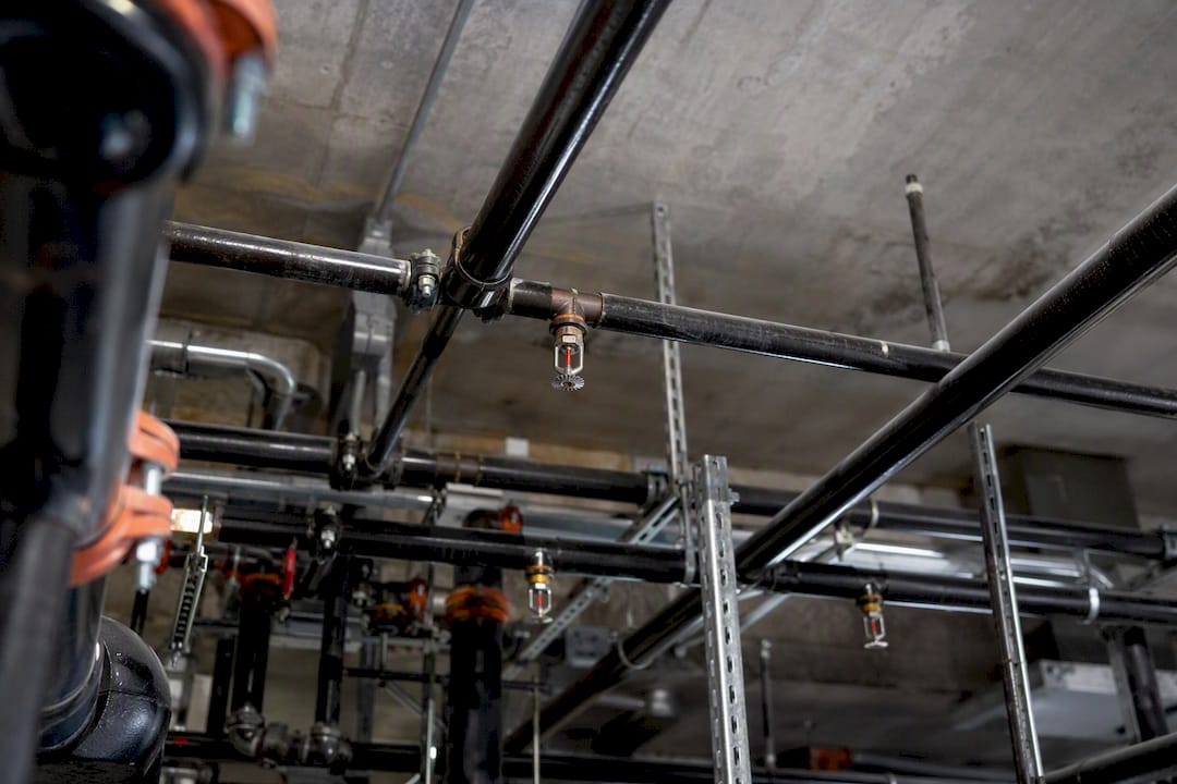
Assume each sprinkler covers 12 m², giving a per-head flow requirement of 6.1 × 12, or roughly 73 L/min. With a K-factor of 80 (metric, L/min per bar^0.5), solving Q = K√P backward gives a required pressure near 0.83 bar at the remote head, comfortably above the NFPA 13 minimum equivalent to 7 psi (about 0.48 bar).
Moving from the remote head toward the riser, each successive branch line adds its own head flow, and friction loss accumulates across every pipe segment based on the assumed C-factor, commonly 120 for standard black steel pipe. By the time the calculation reaches the base of the riser, total demand typically lands 15 to 25 percent above the ideal flow once friction and elevation are included, which is why the ideal figure is a starting point, never the final specified demand. A plan reviewer will always ask for the K-factor datasheet, the assumed C-factor, and any fitting equivalent-length table used to reach the final number.
What Are the Most Common Sprinkler Design Errors?
Occupancy misclassification causes more downstream problems than any other single mistake. An undersized classification produces a system that cannot control the fire it is meant to control; an oversized one inflates water supply requirements and pump costs without a corresponding safety benefit.
Other recurring errors show up in plan review consistently:
- Using a catalog K-factor that does not match the actual listed sprinkler model specified on the schedule.
- Mixing imperial and metric inputs mid-calculation without converting consistently.
- Applying the 3,000 ft² design area as a default rather than confirming the unsprinklered combustible concealed space condition that actually triggers it.
- Ignoring elevation loss on multi-story risers or velocity pressure effects on higher-flow branch lines.
Pro Tip: Document the trade-off explicitly whenever you select a large K-factor sprinkler to reduce required pressure. It lowers pipe sizing needs but raises per-head flow, which can push total demand higher at the fire pump and water supply connection than a smaller K-factor design would. Reviewing these trade-offs early avoids late-stage redesigns; FutureGen Consulting’s guide on sprinkler system design mistakes covers several more field-observed errors worth checking against your own deliverable.
Quick Reference: Conversions and Submission Checklist
Attach the NFPA 13 edition referenced, the exact table and row used, K-factor datasheets, assumed pipe C-factor, and a full hydraulic calculation summary with every submission.
When Should You Escalate a Sprinkler Design for Specialist Review?
Complex storage arrangements, unusual combustible loads, hybrid occupancies, or a limited water supply all warrant a second set of eyes beyond standard calculation checks. Document every assumption and alternative you evaluated. That record is what protects the design, and you, when a reviewer asks why.
How FutureGen Consulting Supports Sprinkler Design and Hydraulic Calculations
Selecting the correct design density is only the first step. Turning it into a stamped, submittable package requires accurate hydraulic calculations, coordination with pump and water supply data, and a set of drawings that satisfies the AHJ on the first pass.

FutureGen Consulting handles the full technical package many engineering teams outsource rather than staff in house: hydraulic calculations built on current NFPA 13 single-point criteria, plan-ready stamped deliverables, code compliance review, and construction support through final inspection. For developers, contractors, and property managers in Ontario and Alberta managing sprinkler design alongside fire alarm, HVAC, and electrical scope on the same project, having one firm coordinate all of it removes a common source of delay at permit review. If your next project needs sealed sprinkler hydraulic calculations or a second opinion on a design density selection before submission, FutureGen Consulting’s fire and life safety design services are the place to start that conversation.
Sources
- NFPA 13 standard development | NFPA
- Basics of fire sprinkler calculations: selecting the design area in the density/area method
- Sprinkler system hydraulics (PRC-12) | AXA XL Risk Consulting
- Fire sprinkler hydraulic calculations: what happened to density/area curves? | QRFS blog
- Water demand requirements — hydraulic calculation methods | UpCodes