
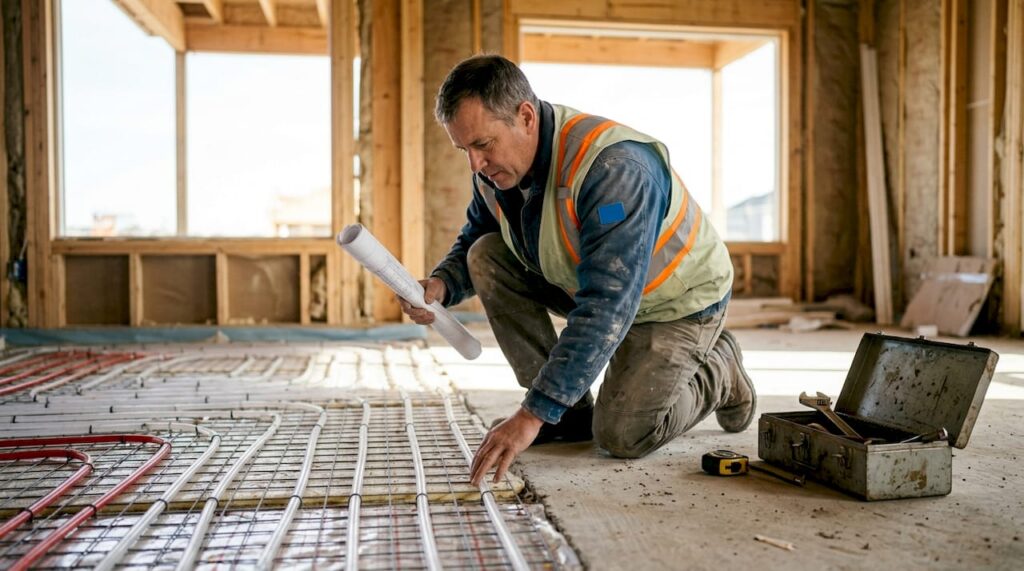
Radiant floor heating design is the process of planning an underfloor heating system by mapping pipe layout, selecting a heat source, and matching system parameters to flooring materials and zone-specific heat loss. The industry term for the most common residential version is “hydronic radiant heating,” which circulates warm water through tubing embedded in or beneath the floor. Ontario builders and homeowners who get this design right gain silent, even warmth, better indoor air quality, and measurable energy savings compared to forced air. Getting it wrong means cold spots, warped floors, and expensive retrofits.
What are the critical design factors in radiant floor heating?
Pipe spacing is the single most consequential variable in any radiant floor heating design. IRC 2024 guidelines specify that typical spacing runs 9–12 inches on center, with tighter 6-inch spacing required in high-heat-loss zones such as exterior walls, entryways, and rooms with large glazing. Wider 12–18 inch spacing suits well-insulated interior zones where heat loss is minimal. Choosing the wrong spacing for a given zone produces uneven surface temperatures and forces the boiler or heat pump to work harder than necessary.
Loop length is equally critical. Single pipe loops should not exceed roughly 100 meters. Beyond that threshold, circulator pumps cannot overcome friction losses, and the far end of the loop runs noticeably cooler than the supply end. That temperature differential translates directly into cold spots on the floor surface.

Operating temperature is a design factor that many builders still underestimate. Modern hydronic systems are designed to run at 40°C–50°C supply water temperature, not the 70°C–80°C range associated with older cast-iron radiator systems. Lower operating temperatures align with air-source and ground-source heat pumps, which produce heat most efficiently at exactly this range. Designing for high temperatures with a modern heat pump wastes energy and shortens equipment life.
Key design factors to verify before finalizing any floor heating layout:
- Zone heat loss calculation: Confirm BTU/hr per square foot for each room before selecting pipe spacing.
- Loop length limits: Keep each circuit under 100 meters to maintain balanced flow.
- Supply water temperature: Target 40°C–50°C for heat pump compatibility.
- Flow rate balance: Size the circulator pump to deliver equal flow across all loops.
- Manifold location: Place the manifold centrally to minimize supply and return pipe runs.
Pro Tip: Run a residential heat loss calculation for each zone independently before drawing a single pipe. A room-by-room calculation prevents the most common design error: applying one pipe spacing across an entire floor plan that has wildly different heat loss values.
How does flooring material affect underfloor heating performance?
Flooring material directly controls how much heat reaches the room and how quickly the system responds to a thermostat call. Tile and stone conduct heat rapidly and efficiently, making them the best performers over hydronic tubing. Thick carpet and dense hardwood act as insulators, reducing heat output and requiring the system to run at higher water temperatures or tighter pipe spacing to compensate.
Wood flooring introduces a structural risk that tile does not. Surface temperature variations exceeding 3°F across a wood floor can cause cupping, gapping, or warping over time. This means the system must be designed to deliver stable, uniform surface temperatures, not just adequate average warmth. Engineered hardwood handles temperature cycling better than solid wood, and most manufacturers specify a maximum floor surface temperature of 27°C.
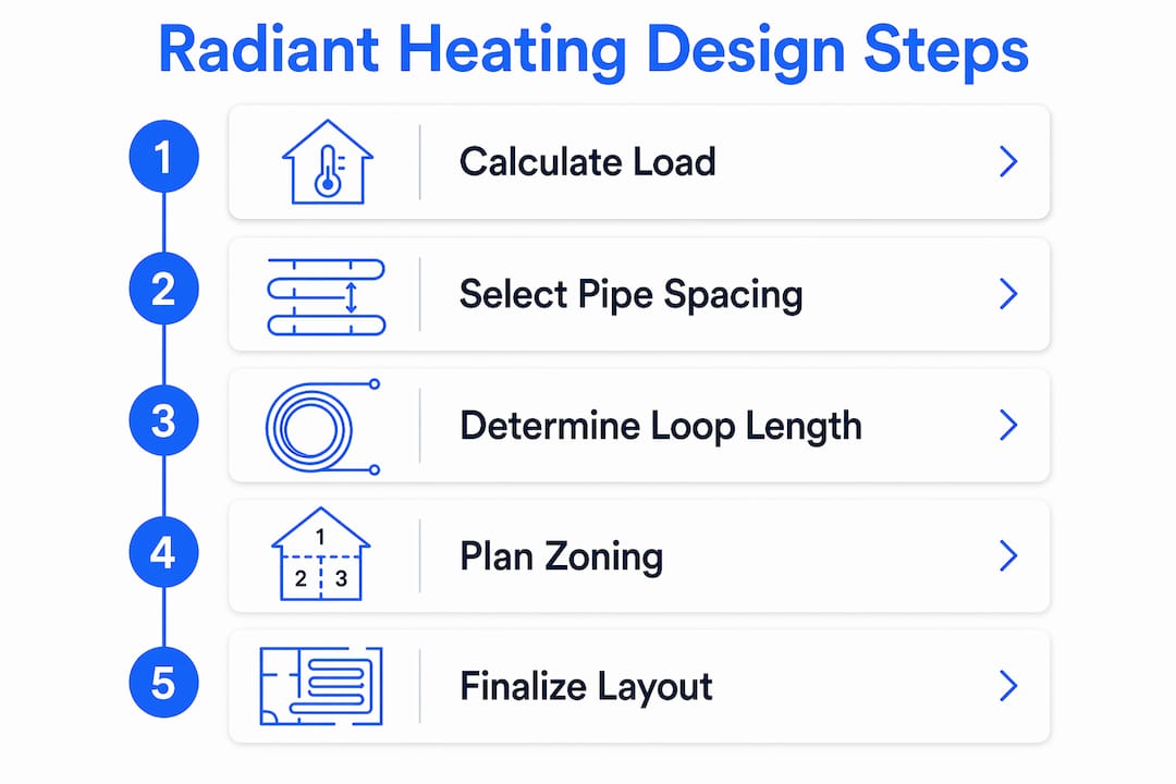
The installation method under wood subfloors adds another layer of complexity. Aluminum heat transfer plates are required in staple-up radiant systems installed beneath wood subfloors. Without them, an air gap forms between the tubing and the subfloor, and that air gap acts as insulation, cutting heat output significantly. The plates conduct heat laterally across the subfloor surface, eliminating hot stripes directly above the tubing.
A practical sequence for matching pipe design to flooring type:
- Identify the finished floor material for each zone before finalizing pipe spacing or depth.
- For tile and stone zones: Use standard 9–12 inch spacing at the depth specified by the slab design.
- For engineered wood zones: Tighten spacing to 6–9 inches and cap supply water temperature to protect the floor finish.
- For carpet zones: Reconsider the system entirely. Carpet with a pad over radiant tubing often requires water temperatures that negate the efficiency advantage.
- Install aluminum transfer plates in all staple-up applications under wood subfloors without exception.
Pro Tip: Specify the finished flooring material in writing before the mechanical engineer finalizes the pipe layout. A last-minute flooring change from tile to hardwood can require redesigning the entire zone’s spacing and temperature parameters.
How to plan system zoning and layout for optimal comfort
Zoning is the practice of dividing a building into independently controlled heating areas, each served by its own loop or group of loops from a central manifold. Proper zoning with individual room control improves both comfort and efficiency by allowing targeted temperatures and eliminating heat delivery to unoccupied spaces. A bedroom zone set to 18°C at night does not need to run at the same output as a bathroom zone set to 22°C.
Manifold placement determines how efficiently the system distributes flow. Placing the manifold centrally within the served area minimizes the length of supply and return piping between the manifold and each loop. Long supply runs outside the heated zone waste energy and create temperature drop before water even reaches the tubing. In a two-story Ontario home, a manifold on each floor typically outperforms a single basement manifold serving the entire building.
Pipe layout pattern affects surface temperature uniformity. The two standard patterns are the serpentine and the counter-flow spiral, also called the “snail” pattern. The serpentine runs supply and return in parallel passes across the zone, which creates a temperature gradient from one side of the room to the other. The counter-flow spiral interleaves supply and return passes, so warm and cooler water alternate across the floor surface, producing more uniform temperatures. The spiral pattern is preferred in living areas where comfort is the priority.
CAD-based layout tools allow engineers to model loop lengths, flow rates, and surface temperatures before installation begins. This step catches imbalanced loops, identifies zones where pipe spacing needs adjustment, and confirms that the manifold can serve all circuits within acceptable pressure parameters. Skipping the CAD step and relying on field estimates is the most reliable way to produce a system with chronic comfort complaints.
What are the advantages and limitations of radiant vs forced air?
Hydronic radiant heating systems are 20–30% more energy efficient than forced-air systems. The primary reason is that water transports thermal energy far more effectively than air, and radiant systems eliminate the duct losses that reduce forced-air efficiency in most residential buildings. That efficiency gap widens further when the radiant system is paired with a modern heat pump operating at low supply temperatures.
Comfort differences are real and measurable. Radiant systems deliver silent, even warmth without the air movement that carries dust, allergens, and noise through a building. Forced-air systems cycle on and off, creating temperature swings and drafts. For Ontario homeowners with allergies or young children, the air quality difference alone often justifies the investment.
The limitations of radiant heating are equally real and must be addressed in the design phase.
| Factor | Radiant floor heating | Forced air |
|---|---|---|
| Energy efficiency | 20–30% higher than forced air | Baseline reference |
| Comfort | Even, silent, draft-free | Cycling, air movement present |
| Air quality | No air distribution, lower dust | Duct-distributed allergens |
| Cooling capability | None built in | Integrated with central AC |
| System response time | Slower, thermal mass dependent | Fast response |
| Installation complexity | Higher, especially in retrofits | Lower in new construction |
Radiant systems cannot provide cooling, which means Ontario homeowners must plan a separate cooling solution. Ductless mini-split systems are the most common pairing, providing air conditioning without requiring ductwork. Hybrid approaches that use radiant heat in primary living areas and forced air in other zones are also common, balancing comfort, efficiency, and cooling integration across the building.
Key Takeaways
Effective radiant floor heating design requires zone-specific pipe spacing, loop length discipline, low-temperature operation, and flooring-matched system parameters to deliver consistent comfort and energy efficiency.
| Point | Details |
|---|---|
| Pipe spacing is zone-specific | Use 6-inch spacing in high-heat-loss zones; 12–18 inches in well-insulated interior areas. |
| Loop length has a hard limit | Keep each circuit under 100 meters to prevent pressure drops and cold spots. |
| Operating temperature matters | Design for 40°C–50°C supply water to align with heat pump efficiency. |
| Flooring material changes the design | Tile and stone perform best; wood requires temperature limits and aluminum transfer plates. |
| Zoning and layout require CAD modeling | Counter-flow spiral patterns and central manifold placement produce the most uniform results. |
What I’ve learned designing radiant systems for Ontario homes
After reviewing radiant heating projects across Ontario, one pattern stands out: most comfort failures trace back to decisions made before a single pipe was installed. The design phase is where the system either works or doesn’t, and the most expensive mistakes are the ones that get buried in concrete.
The shift to low-temperature hydronic design is the most important technical change in this field over the past decade. Builders who still specify systems based on older high-temperature boiler logic end up with oversized equipment, higher operating costs, and heat pumps running outside their efficient range. Designing for 40°C–50°C supply water is not a compromise. It is the correct engineering standard for 2026 residential construction.
Flooring decisions made after the mechanical design is complete cause more problems than any other single factor. A client who switches from tile to engineered hardwood after the pipe spacing is set may end up with a system that runs too hot for the floor or too cool for the room. Locking in flooring specifications before the mechanical engineer finalizes the layout is a project management discipline, not just a design preference.
The integration of professional HVAC design with radiant system planning is where firms like Futuregenconsulting add the most value. Heat loss calculations, loop modeling, and manifold sizing are not tasks that benefit from field estimation. They require engineering rigor, and the cost of getting them right at the design stage is a fraction of the cost of correcting them after installation.
— Sanjay
Futuregenconsulting’s approach to radiant heating system design
Futuregenconsulting brings over 30 years of MEP engineering experience to residential and commercial radiant floor heating projects across Ontario. The firm’s mechanical engineers perform zone-specific heat loss calculations, CAD-based pipe layout modeling, and full system integration with heat pumps and supplementary cooling to produce designs that perform as specified from day one.

Every radiant heating project starts with a detailed load analysis, not a template. Futuregenconsulting tailors pipe spacing, loop lengths, and manifold configurations to the actual thermal characteristics of each building. Builders and homeowners who want a system that delivers consistent comfort and measurable energy efficiency can review Futuregenconsulting’s HVAC system design services or contact the team directly through the MEP engineering services page.
FAQ
What is radiant floor heating design?
Radiant floor heating design is the engineering process of planning pipe layout, heat source selection, and zone configuration for an underfloor heating system. The goal is to deliver even, efficient warmth matched to the specific heat loss and flooring conditions of each room.
How far apart should radiant floor pipes be spaced?
Pipe spacing typically runs 9–12 inches on center in standard zones, with tighter 6-inch spacing in high-heat-loss areas near exterior walls or large windows, per IRC 2024 guidelines.
What flooring works best over radiant heating?
Tile and stone conduct heat most efficiently and are the top choice for radiant systems. Engineered hardwood is acceptable with temperature controls in place; thick carpet significantly reduces heat output and is generally not recommended.
Can radiant floor heating also cool a home?
Radiant floor systems cannot provide cooling. Ontario homeowners typically pair radiant heat with ductless mini-split systems or a separate forced-air cooling unit to cover summer comfort needs.
How does radiant heating compare to forced air for energy efficiency?
Hydronic radiant systems are 20–30% more energy efficient than forced-air systems, primarily because water transfers heat far more effectively than air and radiant systems eliminate duct heat losses entirely.